1.1 UNPACKING
• Removeall packagingmaterial.
• Removeseparateaccessorybox.
• Removecarton off the generator.
1.1.1 ACCESSORYBOX
Checkall contents(Figure1). If any parts aremissing or damaged
locatean authorizeddealerat 1=888=436=3722.
Contentsinclude:
• 2-Axle Pins • Oil Filter
• 2- WheelSpacers • Air Filter
• 2- HairPins • SparkPlug
• 2- Wheels • SparkPlugWrench
• 1 - FrameFoot • ShopTowel
• 2 - FrameBolts • 2 - FrameWashers
• 2-Vibration Mounts • Oil Funnel
• 4 - FlangeNuts 12 Volt Adaptor PlugCharger
• 2 - 1 Quart SAE30 Oil Bottles
Figure 1 - Accessory Boxes
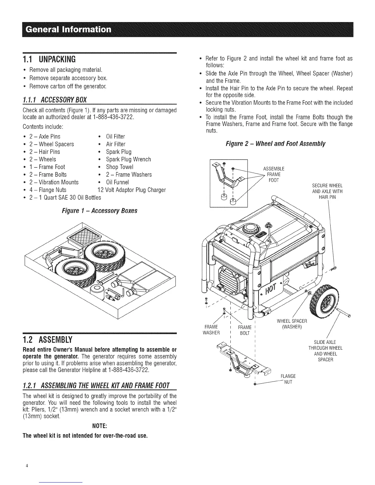
• Referto Figure 2 and install the wheel kit and frame foot as
follows:
• Slidethe Axle Pin throughthe Wheel,Wheel Spacer (Washer)
andthe Frame.
• Install the Hair Pinto the Axle Pinto securethe wheel. Repeat
forthe oppositeside.
• Securethe VibrationMountsto the FrameFootwith theincluded
locking nuts.
• To install the Frame Foot, install the Frame Bolts though the
FrameWashers,Frameand Framefoot. Securewith the flange
nuts.
Figure 2 - Wheel and Foot Assembly
FOOT
SECUREWHEEL
ANDAXLEWITH
HAIRPIN
1.2 ASSEMBLY
Read entireOwner's Manual beforeattempting to assemble or
operate the generator. The generator requires some assembly
prior to using it. If problemsarise when assemblingthe generator,
pleasecall the GeneratorHelplineat 1=888=436=3722.
1.2.1 ASSEMBLINGTHEWHEELKITANBFRAMEFOOT
Thewheelkit is designedto greatly improvethe portability of the
generator.You will needthe following tools to install the wheel
kit: Pliers,1/2" (13mm) wrench and a socket wrench with a 1/2"
(13mm) socket.
NOTE:
The wheel kit is notintendedfor over-the-roaduse.
FRAME
WASHER
I FRAME
I BOLT
I
I
WHEELSPACER
(WASHER)
FLANGE
SLIDEAXLE
THROUGHWHEEL
ANDWHEEL
SPACER
 Loading...


