Section 1 AC Diagnostic Tests
Diagnostic Repair Manual 15
Results
1. If unit is overloaded, reduce load.
2. If load is within limits but frequency and voltage still
drop excessively, refer to flow chart.
Overloading a generator in excess of its rated wattage
capacity can result in damage to the generator and to
connected electrical devices. Observe the following to
prevent overloading unit:
• Add up total wattage of all electrical devices to be
connected at one time. This total should NOT be
greater than the generator's wattage capacity.
• The rated wattage of lights can be taken from light
bulbs. The rated wattage of tools, appliances and
motors can be found on a data label or decal
affixed to the device.
• If the appliance, tool or motor does not give
wattage, multiply volts times ampere rating to
determine watts (volts x amps = watts).
• Some electric motors, such as induction types,
require about three times more watts of power for
starting than for running. This surge of power lasts
only a few seconds when starting such motors.
Be sure to allow for high starting wattage when selecting
electrical devices to connect to the generator:
1. Calculate watts needed to start the largest motor.
2. Add to that figure the running watts of all other
connected loads.
Test 12 – Adjust Voltage Regulator
NOTE: Always use the unit specific schematics and
wiring diagrams for brush orientation.
Procedure
1. Remove cover from end of alternator assembly.
2. Remove two screws holding down the voltage
regulator (AVR); refer to Figure 2-3 in Section 1 for
identification.
3. Leave AVR connected to stator and brushes.
4. Set DMM to measure AC voltage.
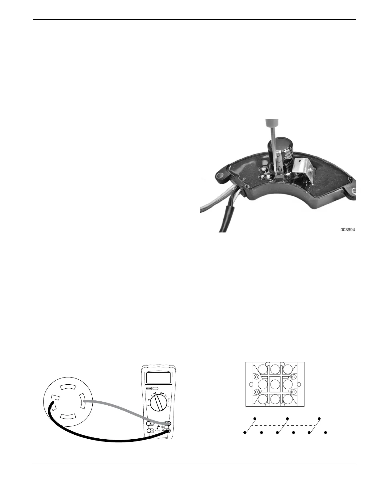
5. See Figure 3-9. Connect DMM across a 240 VAC
receptacle.
Figure 3-9. DMM Test Leads Connected to a 240 VAC
Receptacle
6. Verify all material is clear of the alternator before
proceeding.
7. Set START-STOP-RUN switch to START.
8. See Figure 3-10 for location of adjustment screw.
9. Adjusting screw clockwise will increase voltage,
adjusting counterclockwise will lower voltage.
Results
1. If there is no change in voltage while adjusting,
refer to flow chart.
2. If voltage is correct, stop testing.
Figure 3-10. Voltage Regulator Adjustment Screw
Test 13 – Voltage Changeover Switch
120/240 Position
The voltage change over switch allows the generator to
produce full rated power in the 120 VAC position. The
switch must never be switched while the generator is
running.
1. Remove all the wiring from the voltage change
over switch.
2. Set DMM to read Ohms and zero out the meter.
3. Place the switch in the 120 VAC position and use
the switch schematic and number position to
perform the following tests.
Figure 3-11. Voltage Changeover Switch
3 2 1
6 5 4
9 8 7
7
9461
25 8(COM)
3
3PDT

 Loading...


