Owner’s Manual for Portable Generator 5
Section 2 General Information and Setup
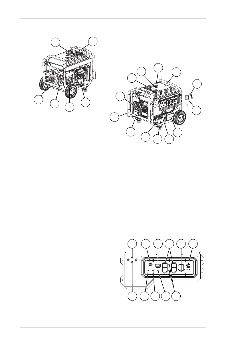
Figure 2-1. Features and Controls
Generator Components
Figure 2-2. Control Panel
21
12
15
13
16
9
18
14
23
10
19
20
17
11
22
010208
010034
24
26
25
29
1 Key Switch Ignition
2 120 Volt AC, 20 Amp GFCI Duplex
Receptacle
3 120/240 Volt AC, 30 Amp Locking
Receptacle
4 Circuit Breakers (AC)
5 Battery Charger Input
6 Hour Meter
7 EFI Fault Indicator Light
8Fuse
9 Grounding Lug
10 Spark Arrestor
11 Muffler
12 Fuel Cap
13 Recovery Hose
14 Carbon Canister
15 Air Filter
16 Recoil Starter
17 Handle
18 Fuel Gauge
19 Roll Over Valve
20 Fuel Tank
21 Oil Drain
22 Oil Fill/Dipstick
23 Battery
24 Fuel Pump
25 Ignition Keys
26 Battery Charger
27 COsense® Shut-Off (RED)
28 COsense® Fault (YELLOW)
29 Oil Filter

 Loading...


