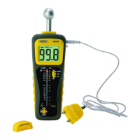
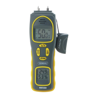
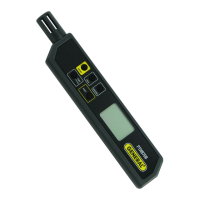
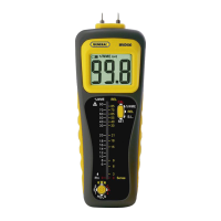
A. Calibration check holes
B. Protective cover
C. 15mm replaceable test pins
D. Indicates display is locked (frozen)
E. Measurement mode indicator (REL shown)
F. Indicates beeper is enabled
G. Indicates battery is weak
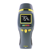
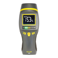
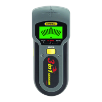
H. Sensing area (on back of meter)
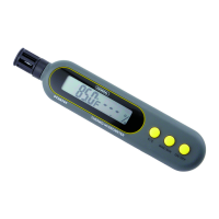
I. Jumbo LCD display
J. Five-function Mode button
K. Four-function button
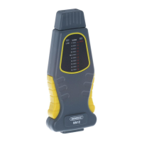
L. Slots for holding protective cover (on bottom of meter)
M. Battery/spare pins compartment cover (on back of meter)
N. Tri-color 40-LED analog bar graph
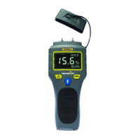
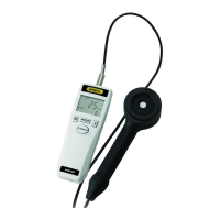
O. Remote probe with 10mm test pins (shown with protective cap on)
P. Jack for remote probe
SETUP INSTRUCTIONS
INSTALL BATTERY
To open the battery compartment, turn the meter over and lift the tab on the
bottom of the battery compartment cover. Remove the cover and set it aside.
Then plug the included 9V battery into the wired socket inside the
compartment. The terminals of the battery and the socket mate in only one
way, with the smaller male terminal plugging into the larger female terminal.
Close the battery compartment by replacing its cover and snapping it shut.
7
 Loading...