10
For Help, call 1-800-35-GENIE or visit www.geniecompany.com
CH
INSTALL M
AGNETIC CARRIAGE
ASSEMBLY ONTO
R
AILS
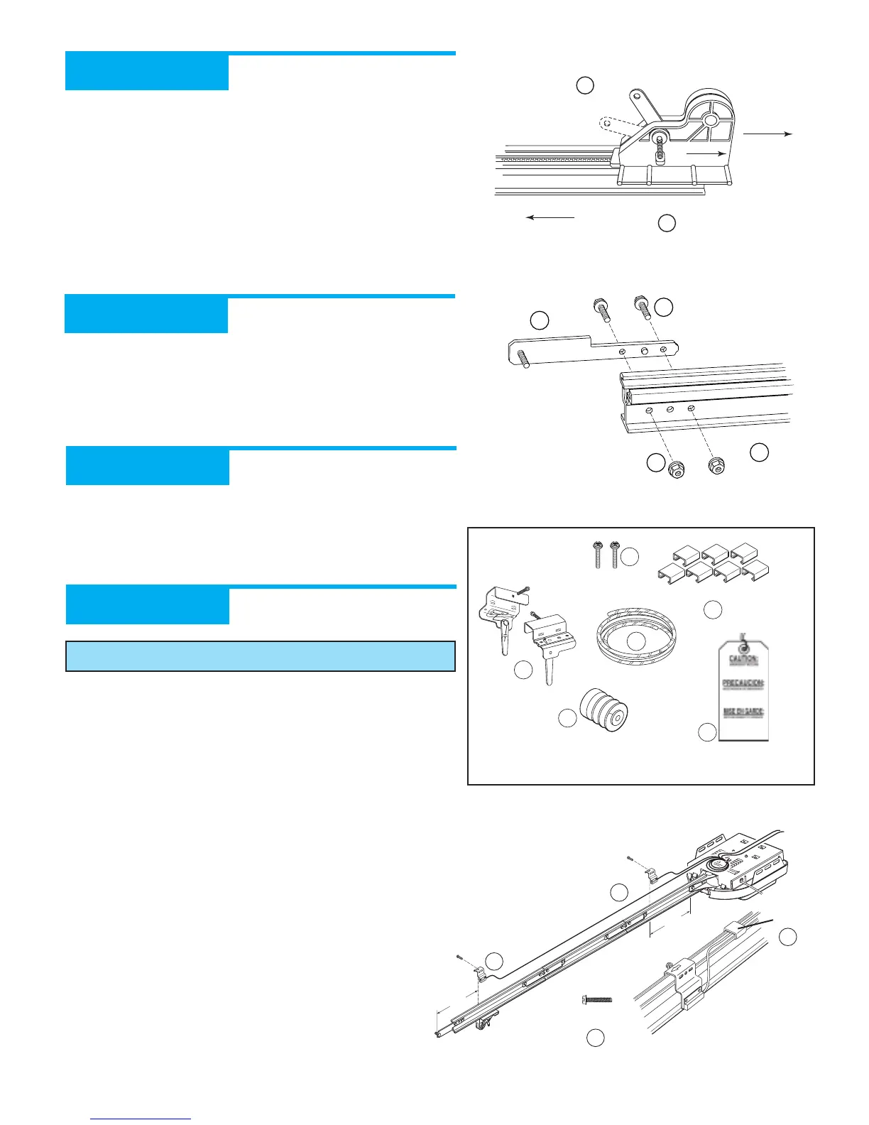
Assembly Step 3:
A Place Magnetic Carriage Assembly Lever in “release” position.
B Slide Magnetic Carriage Assembly into slot on End Rail
Section with arrow pointing away from the Power Head
(Figure 12).
CH ATTACH
RAIL S
TRAP TO END
RAIL SECTION
Assembly Step 4:
A Attach Rail Strap to End Rail Section with 2 (1/4"-20) Hex
Head Bolts and 2 (1/4"-20) Serrated Flange Hex Nuts
(Figure 13).
B Tighten snugly but Do Not over-tighten.
CH A
LIGN RAIL SECTIONS AND
TIGHTEN ALL
BOLTS
Assembly Step 5:
A Align all Rail Sections so Magnetic Carriage Assembly can
slide freely along length of Rail.
BSecurely tighten all fasteners now. Do Not over-tighten.
CH
INSTALL AND CONNECT LIMIT
SWITCHES
Assembly Step 6:
A Turn Opener right side up and support Power Head to avoid
damaging the Light Bulb Sockets.
B Uncoil Limit Switch Wires and retain Twist Ties.
C Place Switches on Rail with arrows pointing away from
Power Head (Figure 14).
D Place Close Limit Switch (Brown Wire) 15" from Rail Strap.
Insert (#8-32 x 1") Hex Head Screw into Switch hole and
finger-tighten until later.
E Place Open Limit Switch (White Wire) 15" from Power Head.
Insert (#8-32 x 1") Hex Head Screw into Switch hole and
finger-tighten until later.
OPEN GREEN PARTS BAG
 Loading...