11
For Help, call 1-800-35-GENIE or visit www.geniecompany.com
NOTE
• Loosen (Do Not Remove) Terminal Block Screws.
• Limit Switch adjustments and securing the Wires
will be done later.
F Lay Wires in channel on top of Rail and secure with Wire Clips
(Figure 14).
G Coil and bundle excess Limit Switch Wires on top of Power
Head with Twist Ties. Leave just enough Wire to reach
Terminals on back of Power Head (Figure 14).
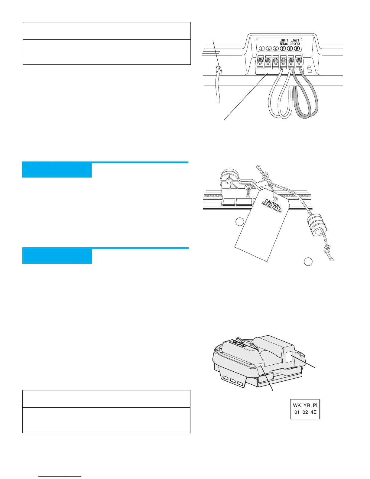
H Turn Opener upside down, and connect Limit Switch Wires to
Power Head Terminal Block (Figure 15):
•Terminal 4: OPEN Limit Switch Wire (white).
•Terminal 5: OPEN Limit Switch Wire (white) and
CLOSE Limit Switch Wire (brown).
•Terminal 6:CLOSE Limit Switch Wire (brown).
CH ATTACH EMERGENCY RELEASE
KNOB,CORD, AND TAG
Assembly Step 7:
A Tie overhand knot at one end of Emergency Release Cord.
B Thread opposite end of Cord through Knob and hole in
Magnetic Carriage Assembly Release Lever (Figure 16).
C Tie overhand knot at this end of Emergency Release Cord.
D Attach Emergency Release Tag to Magnetic Carriage
Assembly Release Lever.
CH
RECORD
OPENER MODEL
AND
S
ERIAL NUMBER
Assembly Step 8:
Please note the following information so it is available if you need
to call us:
Date purchased: ________/________/________
Serial number (Figure 17): _________________________
Model number (Figure 17): _________________________
Dealer Name: _________________________
Dealer Address: _________________________
City: _________________________
State: _________________________
Zip: _________________________
Phone: _________________________
NOTE
Please keep original or photocopy of your sales receipt with
this manual for future reference should service ever be
required.
Antenna
Figure 15 Connect Limit Switch Wires to Power
Head Terminal Block
Terminal
Block
White Limit
Switch wires
Brown Limit
Switch wires
 Loading...