- 27 -
System Hardware Installation
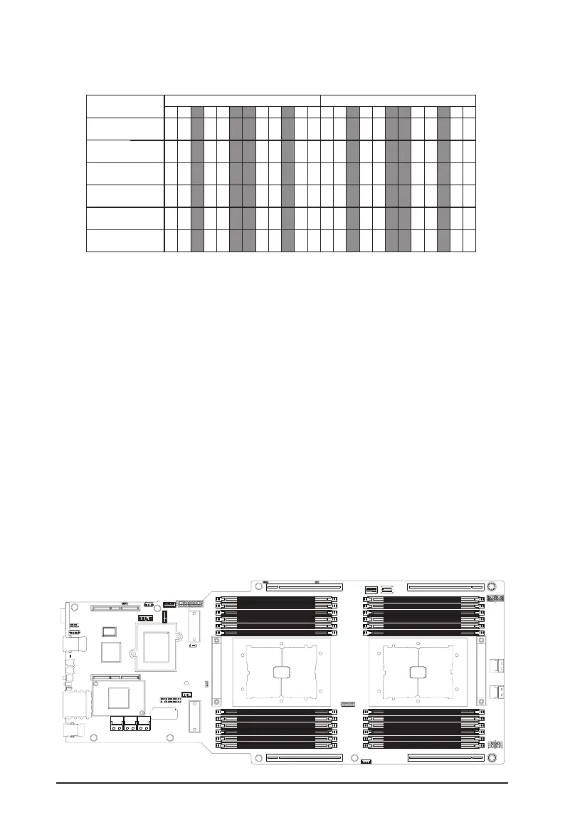
3-4-4 Processor and Memory Module Matrix Table
4 DIMM
Memory Q’ty
for each CPU
CPU1
J0 I0 I1 L0 K0 K1 O1 O0 P0 M1M0 N0
V
1 DIMM
2 DIMM
6 DIMM
8 DIMM
12 DIMM
V
V V
VVVV
VV VV V
V
V
VV
V
V
V
VVVV
VV
V VV
V VV V
CPU0
B0 A0 A1 D0 C0 C1 G1 G0 H0
E1
E0 F0
V
V V
VVVV
VV V V V
V
VV
V V
V VV V
V
V VV
V
V V
V
V
V
V
V
NOTE!
l
There should be at least one DDR4 DIMM per socket.
l
If only one DIMM is populated in a channel, then populate it in the slot furthest away from CPU of that channel.
l
Channel 0's on each memory controller (A/E/C/G, I/M/K/O) must be populated with same total capacity per channel (if populated).
l
Channel 1's on each memory controller (B/F/D/H, J/N/L/P) must be populated with same total capacity per channel (if populated).
3-4-5 Intel Optane DCPMM DIMM Population Rule
Thermal conditions for DCPMM DIMM support:
• The ambient temperature must be at or below 30°C
• The 3rd Generation Intel® Xeon® Scalable Processors used must have a maximum TDP of 270W
• A maximum of 4 pcs 512G DCPMM may be installed
• RDIMM must be installed into CPU0 memory rst
• You must install one RDIMM into any slot #0 of CPU1 before installing the DCPMM.
(e.g.I0/K0/M0/O0)
• The DCPMM must be installed into the DIMM slot #1 next to the corresponding RDIMM
in slot #0 (e.g. if RDIMM is installed into DIMM slot I0, the DCPMM must be installed into
DIMM slot I1)
CPU0 CPU1
J0
/RDIMM Slot
I1
/
Intel Optane DCPMM Slot
I0
/RDIMM Slot
K1
/
Intel Optane DCPMM Slot
L0
/RDIMM Slot
K0
/RDIMM Slot
N0
/RDIMM Slot
O1
/
Intel Optane DCPMM Slot
O0
/RDIMM Slot
M1
/
Intel Optane DCPMM Slot
P0
/RDIMM Slot
M0
/RDIMM Slot
F0
/RDIMM Slot
E1
/
RDIMM Slot
E0
/RDIMM Slot
G1
/
RDIMM Slot
H0
/RDIMM Slot
G0
/RDIMM Slot
C1
/RDIMM Slot
D0
/
RDIMM Slot
C0
/RDIMM Slot
B0
/
RDIMM Slot
A1
/RDIMM Slot
A0
/RDIMM Slot

 Loading...