 Loading...
Do you have a question about the Gigabyte GA-B85M-D3H and is the answer not in the manual?
| Non-ECC | Yes |
|---|---|
| Memory voltage | 1.5 V |
| Memory channels | Dual-channel |
| Memory slots type | DIMM |
| Number of memory slots | 4 |
| Supported memory types | DDR3-SDRAM |
| Maximum internal memory | 32 GB |
| Supported memory clock speeds | 1333, 1600 MHz |
| Processor socket | LGA 1150 (Socket H3) |
| Processor manufacturer | Intel |
| Compatible processor series | Intel Celeron, Intel Pentium |
| Maximum number of SMP processors | 1 |
| USB 2.0 connectors | 2 |
| Power fan connector | No |
| Number of SATA connectors | 6 |
| HDMI version | 1.4a |
| USB 2.0 ports quantity | USB 2.0 ports have a data transmission speed of 480 Mbps, and are backwards compatible with USB 1.1 ports. You can connect all kinds of peripheral devices to them. |
| Audio chip | Realtek ALC892 |
| Component for | PC |
| Power source type | ATX |
| Motherboard chipset | Intel® B85 |
| Audio output channels | 7.1 channels |
| Motherboard form factor | micro ATX |
| Supported storage drive interfaces | SATA, SATA II, SATA III |
| Graphics card | HD Graphics |
| Maximum resolution | 4096 x 2160 pixels |
| Parallel processing technology support | - |
| Bundled software | Intel Rapid Start Technology\\r Intel Smart Connect Technology\\r Intel Small Business Advantage\\r Norton Internet Security |
| BIOS type | UEFI |
| ACPI version | 2.0a |
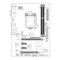
| Depth | 225 mm |
|---|---|
| Width | 244 mm |
Important safety and handling guidelines before installing hardware.
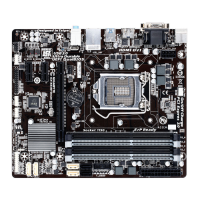
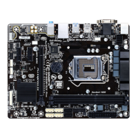
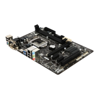
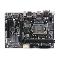
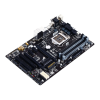
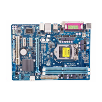
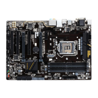
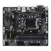
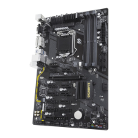
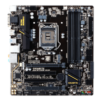
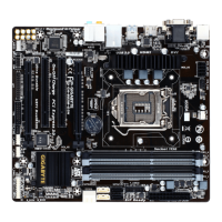
Detailed technical specifications of the motherboard's components and features.
Step-by-step guide for installing the CPU and its cooler.
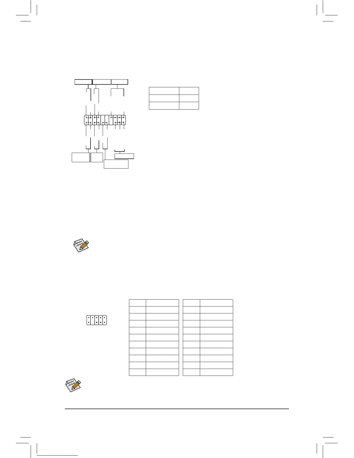
Instructions for installing RAM modules into the motherboard slots.
Guidelines for installing expansion cards like graphics or sound cards.