.45..44.
7. Operation
7.6 AFCI function
Solis inverters have the built-in AFCI function which can detect the arc fault on the DC circuit
and shut down the inverter to prevent a fire disaster.
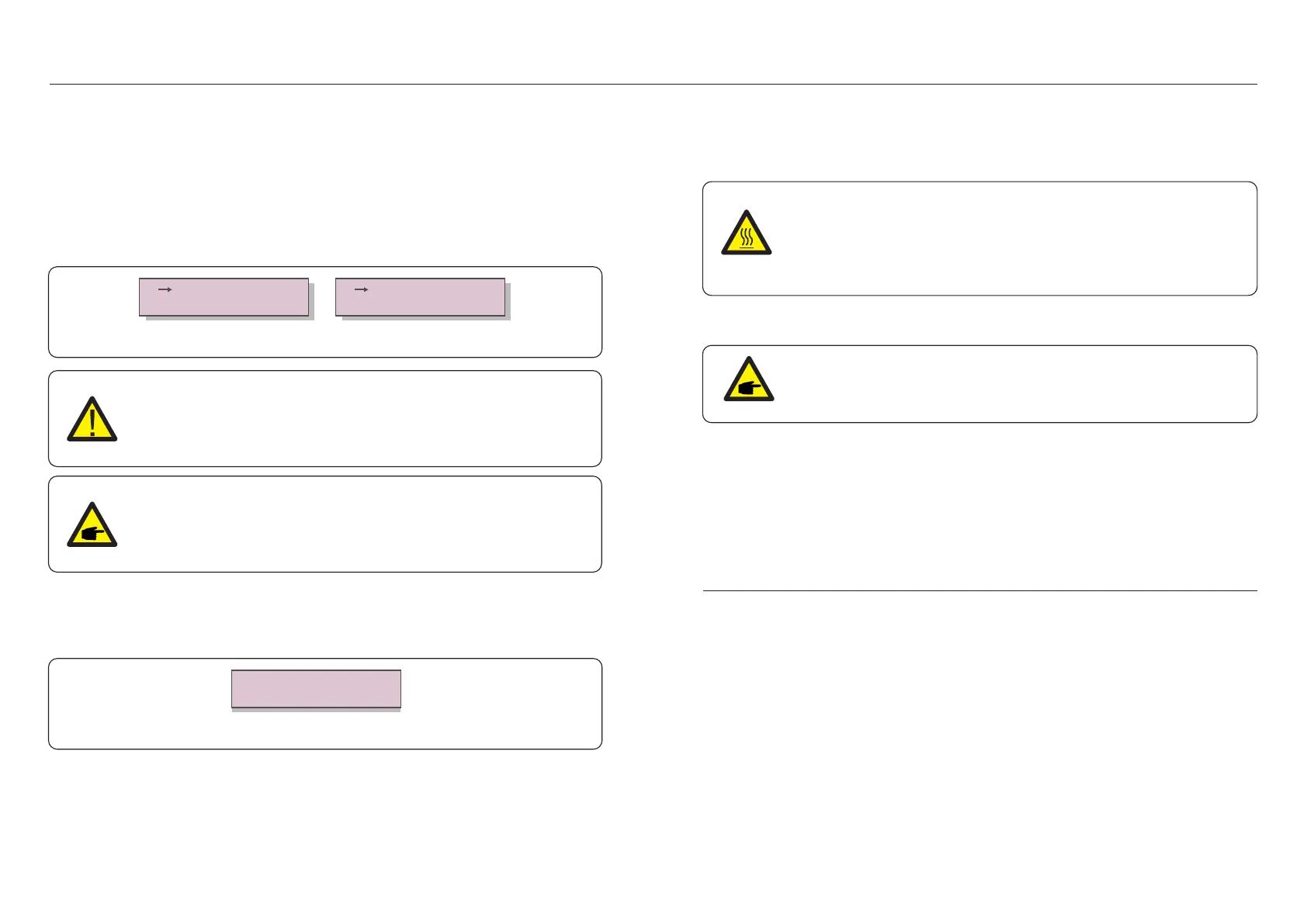
7.6.1 Enable the AFCI function
The AFCI function can be enabled in the following.
Path: Advanced Setting -> Password: 0010 ->Special Settings -> AFCI Set ->
AFCI ON/OFF -> ON
Figure 7.35 Set AFCI
AFCI ON/OFF
AFCI Level
ON
OFF
NOTE:
The setting corresponds to the current status as well which can be used to
inspect the ON/OFF state of the AFCI function.
Warning:
The "AFCI Level" is reserved for Solis technicians ONLY. Do not change the
sensitivity otherwise it will lead to frequent false alarms or malfunctions.
Solis is not responsible for any further damages caused by unauthorized
modifications.
7.6.2 Arc Fault
During the normal operation, if an DC arc is detected, the inverter will shut down
and give out the following alarm:
Installer needs to thoroughly inspect the DC circuit to ensure all the cables are
correctly fastened.
Once the DC circuit issue has been fixed or it is confirmed to be OK, press “ESC” for
3s and wait for the inverter to restart.
ARC-FAULT
Restart Press ESC 3s
Figure 7.36 Arc Fault
Solis Three Phase Inverter does not require any regular maintenance. However,
cleaning the dust on heat-sink will help the inverter to dissipate the heat and increase its life
time. The dust can be removed with a soft brush.
CAUTION:
Do not touch the inverter's surface when it is operating. Some parts of the
inverter may be hot and cause burns. Turn off the inverter (refer to Section
6.2) and wait for a cool-down period before any maintenance or cleaning
operation.
The LCD and the LED status indicator lights can be cleaned with a damp cloth if they are too
dirty to be read.
NOTE:
Never use any solvents, abrasives or corrosive materials to clean the inverter.
The inverter is designed in accordance with the most important international grid-tied
standards and safety and electromagnetic compatibility requirements. Before delivering to
the customer, the inverter has been subjected to several tests to ensure its optimal operation
and reliability.
In case of failure, the LCD screen will display an alarm message. In this case, the inverter
may stop feeding into the grid. The failure descriptions and their corresponding alarm
messages are listed in Table 9.1:
9. Troubleshooting
8. Maintenance
 Loading...