Handling instructions
for GISMA connectors
HI – 2007 - 001
Document: replaces
MV 2000-020,
MV 2000-030 and
MV 2005 - 011
First issue: 15.07.2008
Rev.-Index: -Z-
From: 29.07.2020
Page 37 of 44
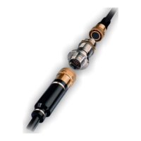
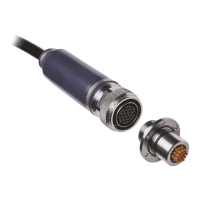
SUBSEA CONNECTORS SERIES 80
7.8.1. General
The series 80 range of connectors has been developed for long term reliable signal and low power
control system applications associated with offshore installations. The subsea pluggable capacity
of these connectors is achieved using pressure compensated electrical inserts employing the
GISMA flushing contact principle.
Connectors are usually supplied with dust caps. The dust caps must be removed prior to mating
the connectors.
For further technical information refer to the catalogue of series 80 or special drawings.
All mild steel sealing interfaces shall be inlayed with Inconel 625, or similar, where no additional
protection can be provided. This is to prevent localised pitting of the interface. If not possible
grease the mounting hole and the supporting surface with corrosion preventing fluid (for example
Fluid Film) as a minimum.
If the connectors are to be left unmated, in seawater, for any length of time pressure watertight
protective cap must be used to protect the pin contacts in the receptacle. Over exposure will
increase the risk of corrosion damage or marine growth on the contact surfaces of the receptacle’s
pin contacts. This could lead to damage to the seals and insulation within the socket contacts.
Plugs do not require full pressure watertight protective cap for protection. GISMA advise the fitting
of POM caps to protect plugs against marine growth. It is good practice to always fit the protective
cap when a connector is unmated topside prior to deployment to provide mechanical protection.
The appropriate test connector must always be used to make electrical contact during testing.
UNDER NO CIRCUMSTANCES a foreign object (such as a screwdriver, test probe, or crocodile
clip) should be used as a test connection as this could damage the seals and insulation. Such
actions will invalidate the warranty of the connector.
Attention: The customer is responsible for the safe operation of the connectors and cable
systems. All necessary protective measures must be taken.
The series 80 range of connectors can be supplied either singularly or as part of a harness
assembly. All series 80 connectors require the following during termination:
Mating test
Insulation Resistance test
High Voltage test
Continuity test
Cable terminations can be performed on-site by GISMA trained personnel or partner companies
where the cable cannot easily be moved or transported. Each series 80 connector has been
hydrostatically tested and electrically proven prior to despatch. Termination of these connectors
should only be undertaken by trained personnel.
7.8.2. Live Mate / Demate
The series 80 range of connectors are designed to be mated / de-mated with POWER OFF.
 Loading...