40
0020008154A
14 Replacement of Parts
14.6 Fan
For access, refer to section 14.1.
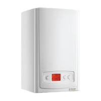
Refer to section 12.3 for removal of the fan, gas valve and
burner assembly.
Remove the gas valve as described in the relevant parts of
section 14.5.
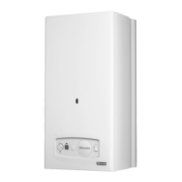
Remove the venturi plate secured with three screws, see
diagram 14.3.
Remove the two screws securing the fan to the gas manifold,
see diagram 14.4, check the gasket and replace if necessary.
NOTE : The 30 fan is secured through an extension piece with
two securing screws, check and replace any seals or gaskets if
necessary.
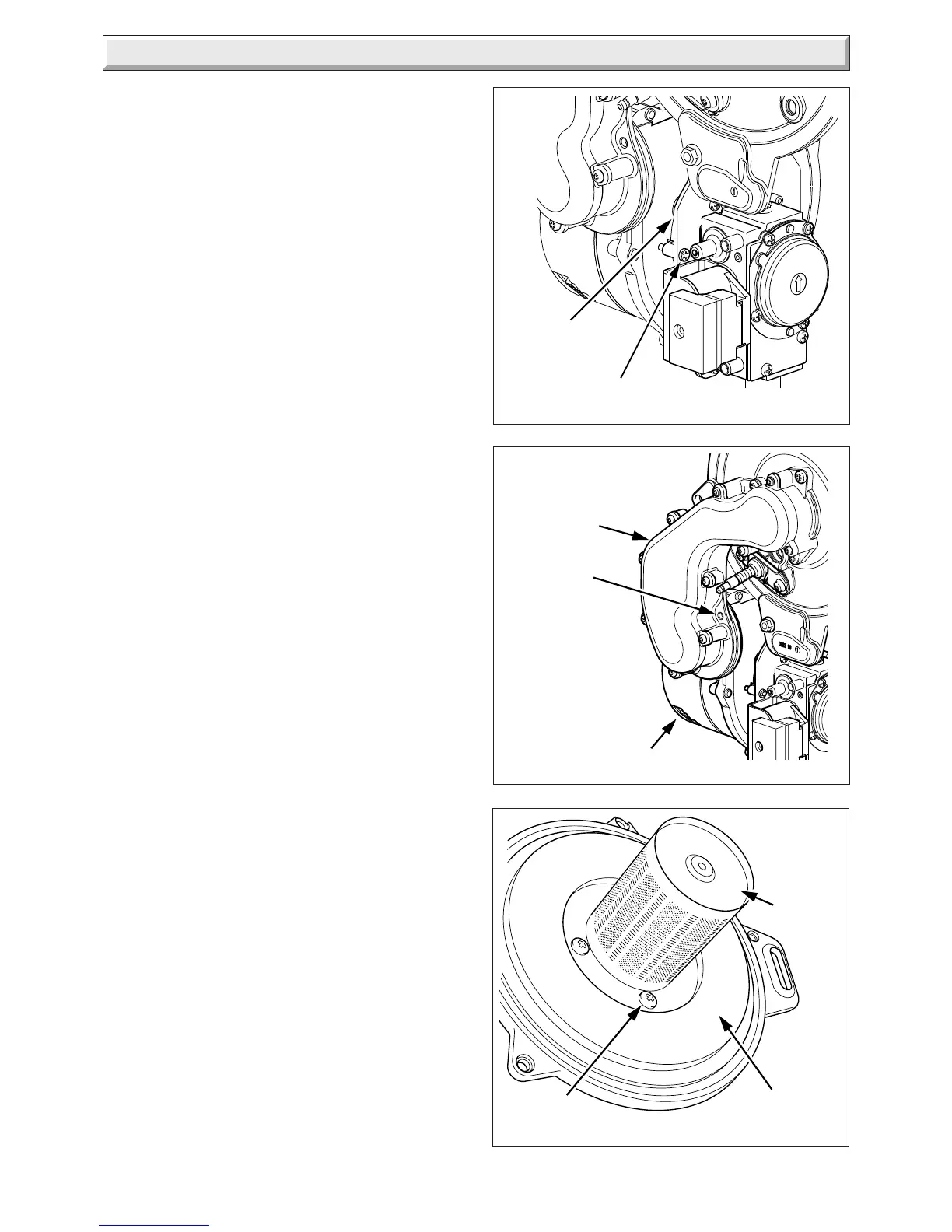
14.7 Burner
For access, refer to section 14.1.
Refer to section 12.3 for removal of the fan, gas valve and
burner assembly.
Remove the four screws that secure the burner, see diagram
14.5.
NOTE: THE BURNER WILL REQUIRE A NEW GASKET
WHEN REFITTED.
Diagram 14.4
Diagram 14.3
SECURING
SCREW (2)
SECURING
SCREW (3)
Diagram 14.5
SECURING
SCREW (4)
VENTURI
PLATE
FAN
GAS
MANIFOLD
BURNER
INSULATION
11486
11485
11487
24cxi Illustrated
 Loading...