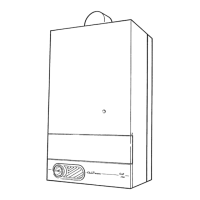
MINIMUM SITING DIMENSIONS FOR
FANNED FLUE TERMINALS
POSITION
MM
A DIRECTLY BELOW AN OPENABLE
WINDOW, AIR VENT, OR ANY
OTHER VENTILATION OPENING 300
B BELOW GUTTER, DRAIN/SOIL PIPE 75
C BELOW EAVES 200
D BELOW A BALCONY OR CAR PORT 200
E FROM VERTICAL DRAIN PIPES AND
SOIL PIPES 75
F FROM INTERNAL OR EXTERNAL
CORNERS 300
G ABOVE ADJACENT GROUND OR
BALCONY LEVEL 300
H FROM SURFACE FACING THE
TERMINAL 600
I FACING TERMINALS 1200
J FROM OPENING (DOOR/WINDOW)
IN CAR PORT INTO DWELLING 1200
K VERTICAL FROM A TERMINAL 1500
L HORIZONTALLY FROM A TERMINAL 300
MINIMUM
SPACING
2816
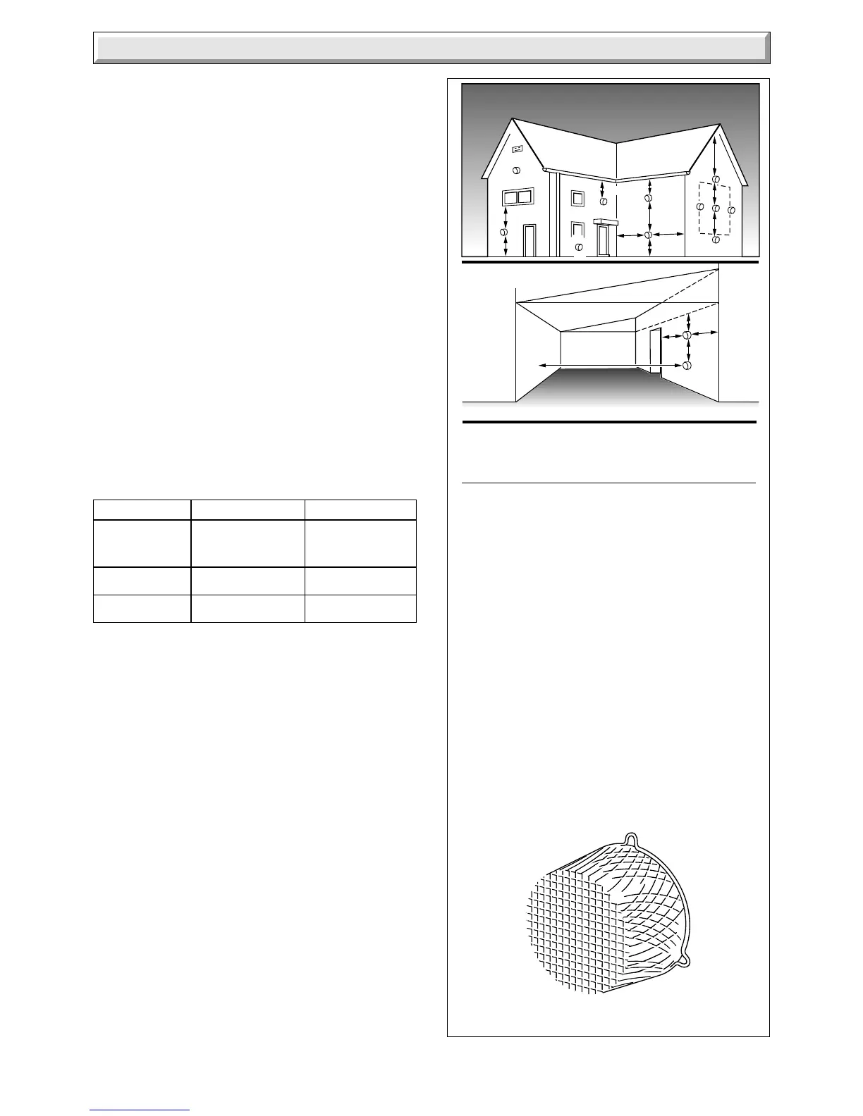
3.6 Terminal Guard
A terminal guard is required if persons could come into contact
with the terminal or the terminal could be subject to damage.
If a terminal guard is required, it must be positioned to provide
a minimum of 50mm clearance from any part of the terminal and
be central over the terminal.
The guard should be similar to that shown in diagram 3.5 and
can be bought from:
Tower Flue Components Ltd
Morley Road
Tonbridge
Kent. TN9 1RA
their type K3.
3.7 Room Ventilation
Ventilation must be provided in accordance with the rules in
force in the countries of destination.
The boiler is room sealed, so where the boiler is fitted in a room
or space, a permanent air vent is not required.
3.8 Cupboard/Compartment Ventilation
If the boiler is to be fitted in a cupboard or compartment,
permanent high and low level air vents must be provided for
ventilation. The vents must have at least the effective areas
shown in Table 2.
Diagram 3.5
Low Vent 264cm
2
40in
2
132cm
2
20in
2
High Vent 264cm
2
40in
2
132cm
2
20in
2
TABLE 2
Position Air from Air Direct
of Room or from
Air Vent Internal space Outside
 Loading...