10
221469B
3 Flue and Ventilation
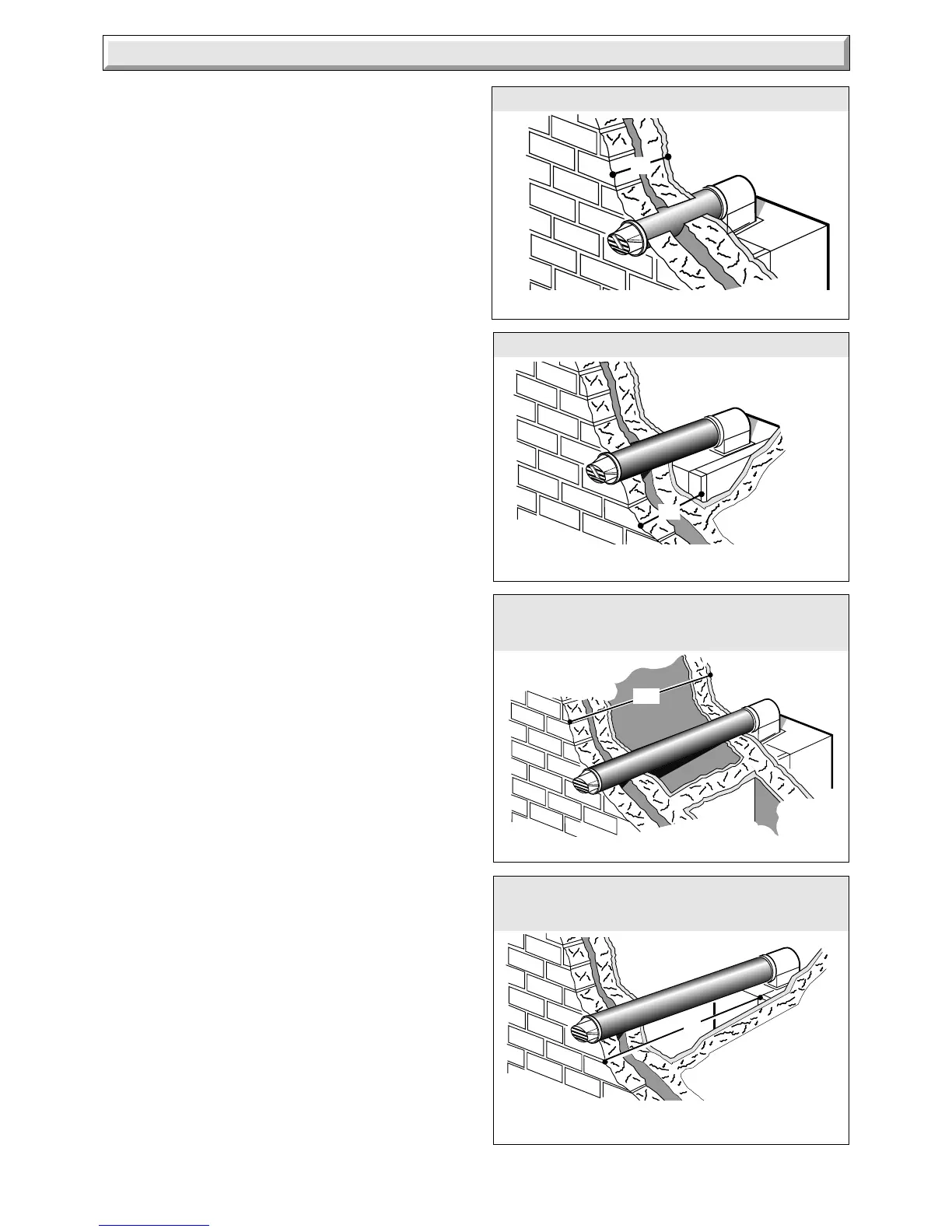
Diagram 3.1
Diagram 3.2
DISTANCE 'Y': 80 TO 343mm
2309
WALL THICKNESS 'X': 75 TO 400mm
Diagram 3.4
SIDE FLUE - STANDARD
Left or Right
SIDE FLUE - LONG
Left or Right
REAR FLUE - STANDARD
'X'
'Y'
'Y'
2311
2308
3.1 Flue
The flue must be installed in accordance with the rules in force
in the countries of destination.
3.2 Flue Position and Length
The air and flue ducting connect to the top of the boiler using the
elbow which can be positioned in one of three possible directions:
Rearward, left or right.
The standard flue is able to provide the duct length range shown
in diagram 3.1 for a rear flue or diagram 3.2 for a side flue.
If a longer flue duct is required, do not extend
the ductings.
A 1, 2 or 3metre flue system and terminal must be used and can
be supplied. This is able to provide the duct length range shown
in diagram 3.3 for rear flue or diagram 3.4 for a side flue.
To make a neat finish to the flue outlet a flue collar kit, part No.
443286, with instructions, is available.
The use of this collar will mean that the flue lengths will need to
be altered, full instructions are given in the kit.
3.3 Terminal Position
The minimum acceptable siting dimensions for the terminal
from obstructions, other terminals and ventilation openings are
shown in diagram 3.5.
The terminal must be exposed to the external air, the position
allowing free passage of air across it at all times.
Car port or similar extensions of a roof only, or roof and one wall,
require special consideration with respect to any openings,
doors, vents or windows under the roof. Care is required to
protect the roof if made of plastic sheeting. If the car port
comprises of a roof and two or more walls seek advice from the
local gas undertaking before installing the boiler.
If the terminal is fitted within 600mm below plastic guttering, an
aluminium shield 1500mm long should be fitted immediately
beneath the guttering or eaves. If the terminal is fitted within
450mm below painted eaves or a painted gutter, an aluminium
shield 750mm long should be fitted immediately beneath the
guttering or eaves.
3.4 Internal Access Flue
The flue can be installed from inside the building, when access
to the outside wall face is not practicable. An internal access kit
can be provided.
3.5 Timber Frame Buildings
If the boiler is to be installed in a timber frame building it should
be fitted in accordance with the Institute of Gas Engineers
document IGE/UP/7/1998. If in doubt seek advice from the local
gas undertaking or Hepworth Heating Ltd.
Diagram 3.3
2310
REAR FLUE - LONG
'X'
1m DISTANCE 'X': 75 TO 898mm
2m DISTANCE 'X': 75 TO 1898mm
3m DISTANCE 'X': 75 TO 2890mm
1m DISTANCE 'Y': 80 TO 833mm
2m DISTANCE 'Y': 80 TO 1833mm
3m DISTANCE 'Y': 80 TO 2833mm
 Loading...