18
221469B
7 Flue Preparation
23342302
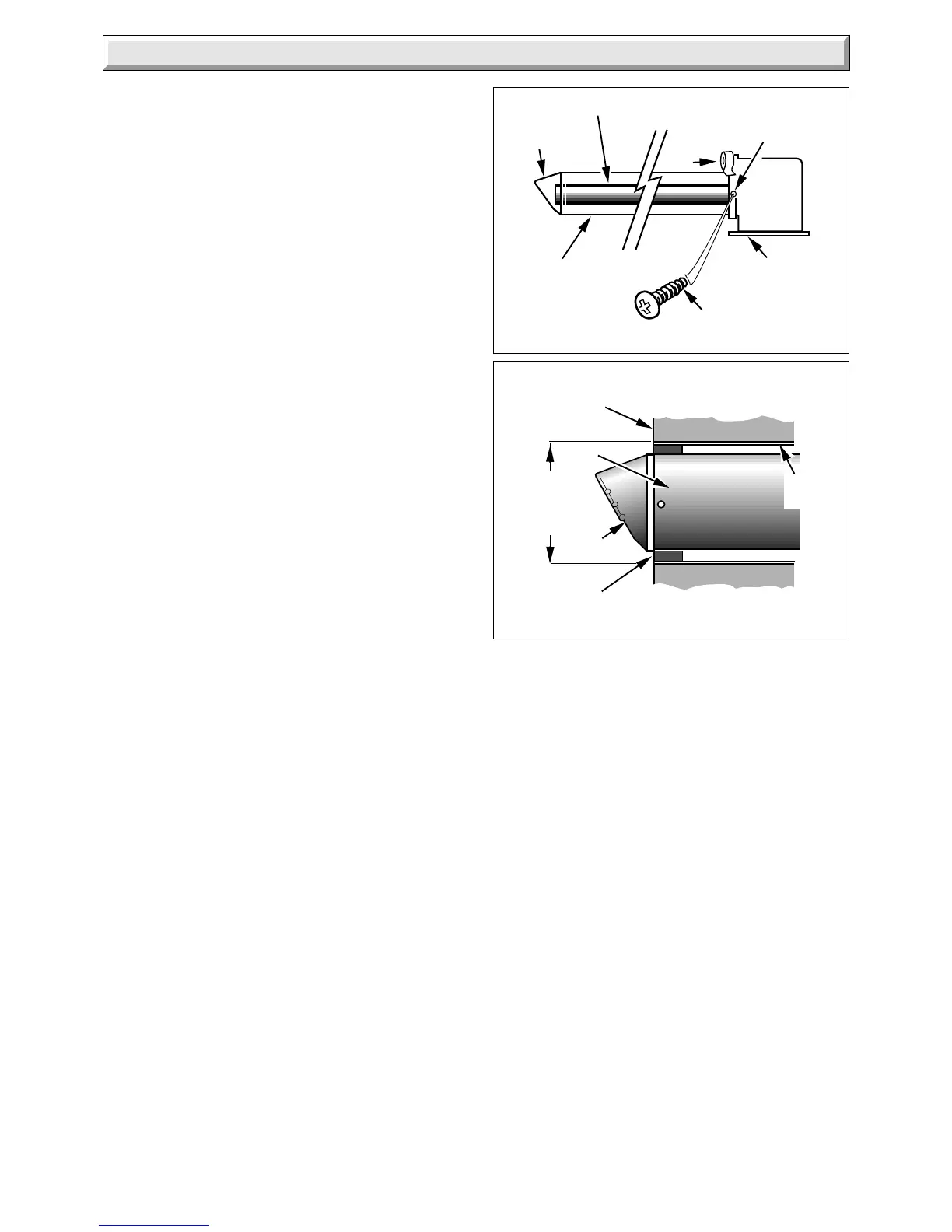
Diagram 7.5
INTERNAL ACCESS
FLUE
TERMINAL
AIR
DUCT
115 DIA.
CORE
DRILLED
HOLE
SEAL
OUTSIDE
WALL FACE
WALL
LINER
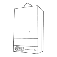
Diagram 7.4
FLUE AIR DUCT
FLUE
ELBOW
SCREW (2)
AIR DUCT
FLUE DUCT
FLUE
TERMINAL
TAPE
3.3 DIA
HOLE IN EACH SIDE
OF THE AIR DUCT
7.4 Air Duct
Locate the flue duct and air duct in the flue elbow, making sure
that the flue duct is located in the flue terminal and the flue elbow
but is free to move to allow for expansion.
Check that the flue terminal is in the correct position and sticking
out the correct distance from the outside wall face, see diagram
7.1 and appropriate diagram 7.2 or 7.3.
Drill a hole, diameter as shown in diagram 7.4, in each side of
the air duct, through the holes in the flue elbow. Secure the air
duct to the flue elbow using the two screws supplied in the loose
items pack.
Seal around the joint between the air duct and the flue elbow
using the tape provided in the loose items pack.
If the boiler is not to be fitted for some time, cover the hole in the
wall.
7.5 Internal Access Flue
If access to the outside wall surface is not practical, the flue
system can be installed from inside. Use of the optional wall
liner kit is required, see diagram 7.5
 Loading...