.....
..
.
...
.
.
.......
..
.
.
..
.
..
...
2
1
3 4 5 6
7
8
9
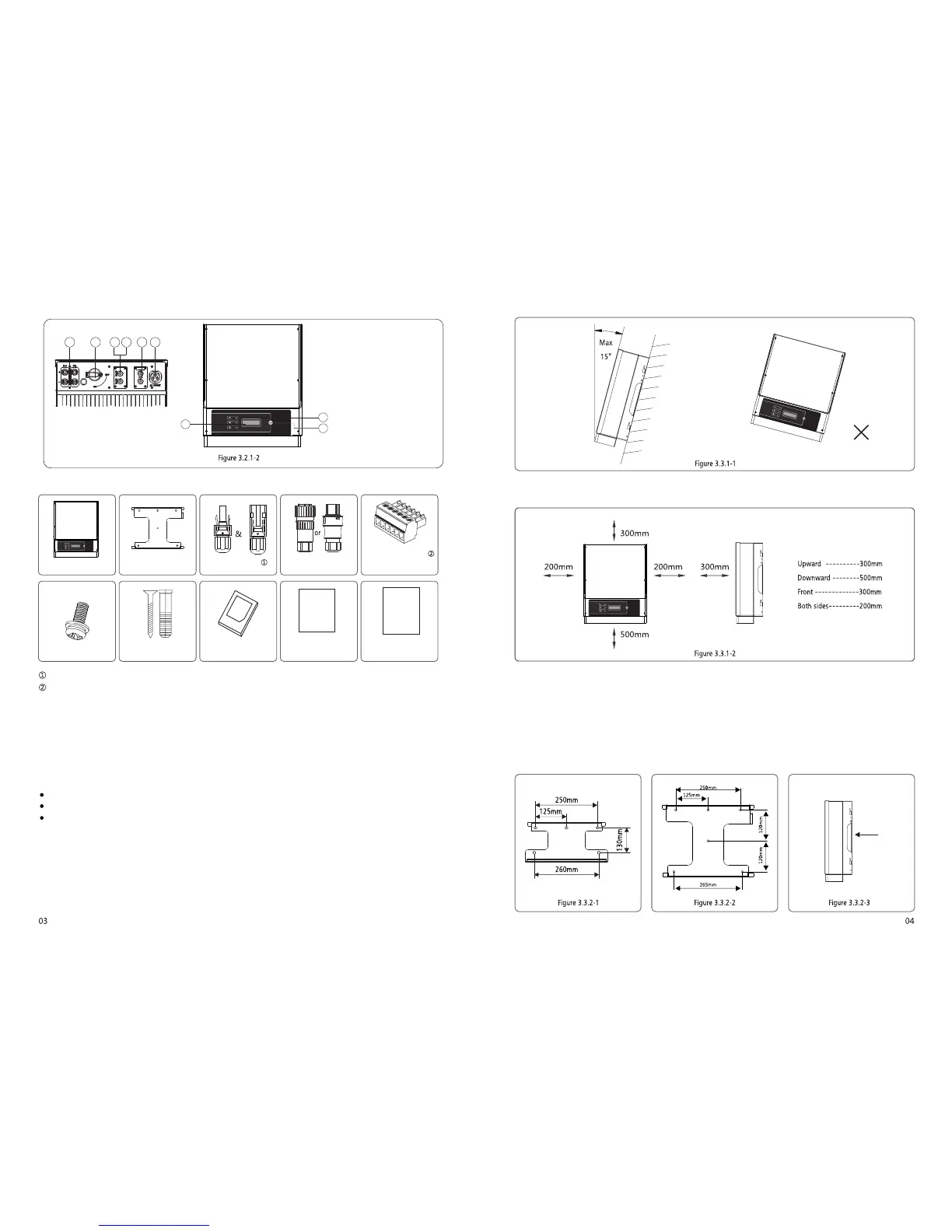
1. PV input terminals
2. DC Switch (Optional)
3. RS-485 port or USB port
4. Wi-Fi antenna port (Optional)
5. CT and DRED function
(Optional)
6. AC output terminal
7. LCD display
8. Indicator lights
9. Button
3.2.2 Package
6Pin Terminalx1
2Pin Terminalx1
AC PlugX1
DC PlugX2pair
Wall-mounted
Bracket x1
Inverterx1
Screwx4
Expansion Boltsx5 Expansion Boltsx5
Wi-Fi
Connection
Guide
Quick
Installation
Guide
Quick Installation
Guidex1
Wi-Fi Connection
Guidex1
(WiFi BOM only)
There is 1 pair of DC connectors in NS Series 1-3KW. and 2 pairs of DC connectors in NS Series 3.6-5KW and DNS Series 3-5KW;
6Pin terminal for RS485 function, 2Pin terminal for CT function.
3.3 Inverter Installation
3.3.1 Selecting the installation location
The following must be considered when selecting the best location for an inverter:
The mount and installation method must be appropriate for the inverter's weight and dimensions.
The location must be well ventilated and sheltered from direct sunlight.
The inverter must be installed vertical or with a backward tilt less than 15. No sideways tilt is allowed. The connection
area must point downwards. Refer to Figure 3.3.1-1.
To allow dissipation of heat, and for convenience of dismantling, clearances around the inverter must be at least:
The installation position shall not prevent access to the disconnection means.
3.3.2 Mounting Procedure
(
referred to Figure 3.3.2-1, NS 3.6kW-5kW & DNS 3kW-5kW referred to Figure 3.3.2-2.
(2) Fix the wall mounting bracket on the wall using the expansion bolts in the accessories bag.
(3) Hold the inverter by the side groove as Figure 3.3.2-3.
(4) Install the inverter on the wall-mounted bracket. NS 1 kW~3kW referred to Figure 3.3.2-4, 3.3.2-5. NS 3.6kW-5kW & DNS
3kW-5kW referred to Figure 3.3.2-6, Figure 3.3.2-7.
1) Use the wall-mounted bracket as a template and drill holes in the wall,10 mm in diameter and 80 mm deep. NS 1 kW~3kW
 Loading...