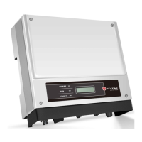
3.4.4 Earth Terminal Connection
The inverter is added earth terminal according to the requirement of EN 50178. It is must that installation person should connect the
terminal to earthing wire.
Position of earth terminal as Figure 3.4.3-1.
The earth connecting terminal is on the side of inverter, illustrated as Figure 3.4.4-1. The customer should select to grounding base on
site condition.
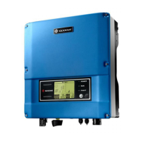
3.4.5 USB Communication
USB cable should be connected as Figure 3.4.5-1.
2.Insert the USB data cable
1.Remove RS485 waterproof assembly
USB interface just for after-sales service team repair invter, shall not use the it for any other purposes.
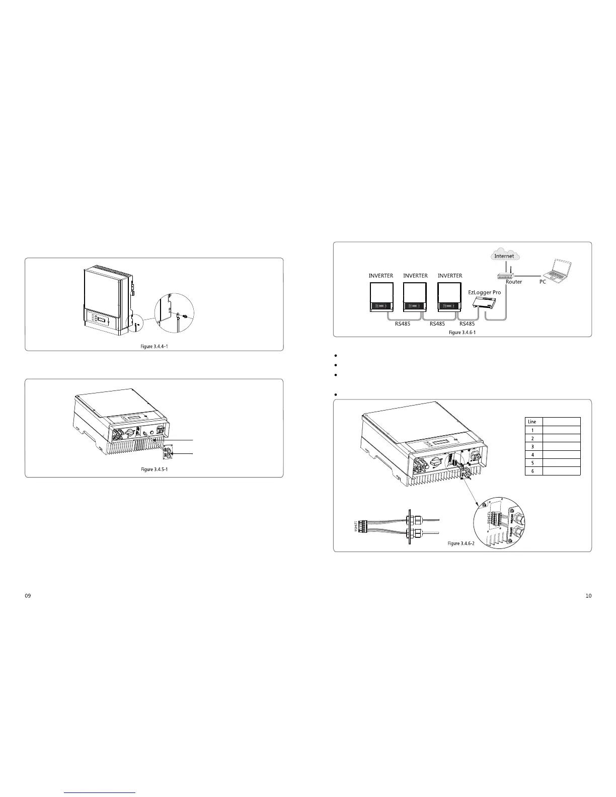
3.4.6 RS485 Communication
This function is only applied to inverters with RS485.
The RS485 interface is used to connect EzLogger Pro and the maximum total length of all connecting cables should not exceed 800m.
RS485 connection is referred to 3.4.6-1.
(1)Connection Procedure:
Put the cable through the components in this order: screw cap, one-hole sealing ring, insulation body and sheet metal parts.
Take the green terminal out of accessory bag. cable should be connected as Figure 3.4.6-2.
Insert the green terminal into the corresponding interior terminal of the inverter. Pull cable softly to maintain the cable not
to be pulled out.
Lock the sheet metal parts onto the box and tighten the screw cap.
(2)Connect the inverter to EzLogger Pro with RS485 cable, and EzLogger Pro to network switch or router with CATSE STP cable.
Function
RS485+
RS485-
Reserved
Reserved
RS485+
RS485-
 Loading...