2
1
/
The inverter complies with IEC62109-2 chapter 13.9. When earth fault occurs,the fault indicator LED on front cover will
light up, and, for wifi inverter, it will email the fault information to customer, for non wifi inverter ,the buzzer in inverter
will keep ringing 1 minute and ring again after half an hour unless the fault is resolved(This function is only available to
Australia/ New Zealand).
3.4.7 Wi-Fi Communication
The Wi-Fi communication function is only applied to WiFi BOX, the detailed configuration instruction can be referred to Wi-Fi
Configuration in the accessory box.
After configuration, please browse http://www.goodwe-power.com to create PV station.
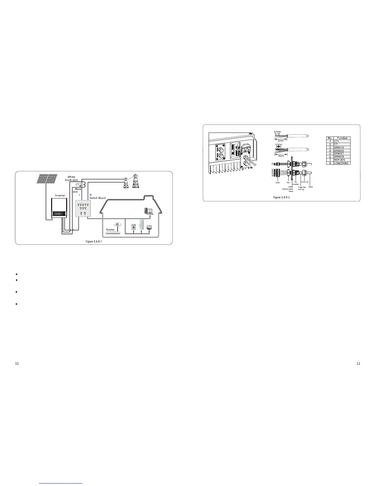
3.4.8 Power Limiting Device & DRED Installation
Connection method of Power Limiting device CT please refer to Figure 3.4.8-1.
NOTE:
2-pin terminal is used to make connection to CT device.You can find it in accessory bag.
6-pin terminal is used to make connection to DRED device. If DRED device is not available, please keep it not connected.
Connection Procedure:
Put the cable through the components in this order: screw cap, one-hole sealing ring, insulation body and sheet metal parts.
Pull out the 6-pin terminal from the socket in the cabinet and take off the resistor which is fixed in it.Cable should be
connected as Figure 3.4.8-2.
Insert the green terminal into the corresponding interior terminal of the inverter. Pull cable softly to maintain the cable not
to be pulled out.
Lock the sheet metal parts onto the box and tighten the screw cap.
1.DRED connection is only available forAustralia and New Zealand.
2.Supported DRM command: DRM0,DRM5,DRM6,DRM7,DRM8.
3.After installation is completed, please set up power limiting function referring to section 4.2(6).
4.Pay attention to the direction of CT when wiring. CT clip should be locked tight. White /Black cable should connect Line 2,
black cable should connect Line 1. Tighten them with screwdriver. Make sure CT cables connected to the right output phase lines
of inverter when in use.
5.Without connection of CT, inverter will show "CT Disconnect". If CT is connected reversely, inverter will show" CT Reverse
"when it enters into on-grid status.
3.4.9 Earth Fault Alarm
 Loading...