7
User Manual V1.1-2022-11-15
03 Product Introduction
No. Parts Description
4 PV Input Terminal Used to connect the PV module DC input cables.
5
COM Port for communication
module or USB.
• Connect a communication module like WiFi, GPRS,
4G, etc. The module type may dier depending
on actual needs.
• Update the software version of the inverter using
a USB ash driver.
6
RS485 Communication Cable
Port(optional)
Used to connect the RS485 Communication Cable.
7
CT/DRED/Remote Shutdown
Communication Cable Port
Used to connect the CT, DRED, or remote shutdown
communication cable.
8 AC Output Terminal
Used to connect the AC output cable, which connects
the inverter and the utility grid.
9 Ventilation Valve -
10 Indicator Indicates working state of the inverter.
11 LCD Used to check the parameters of the inverter.
12 Button Used to select menus displayed on the screen.
13 PE Terminal Used to connect the PE cable.
14 Heat Sink Used to cool the inverter.
15 Mounting Plate Used to install the inverter.
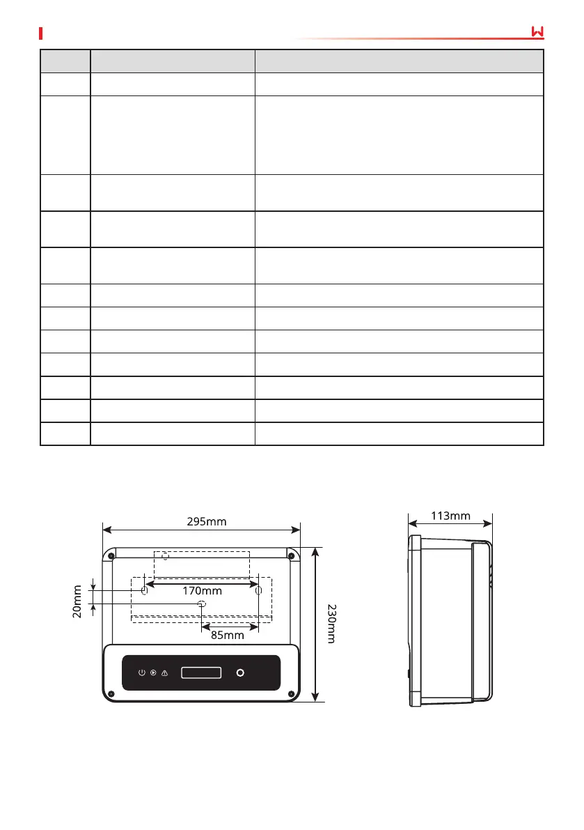
3.4.2 Dimensions
 Loading...