[1]Positive & Negative Plug:
NS series 1 pair;
DNS series 2 pairs.
Max
15°
To allow for dissipation of heat, and for convenience of dismantling, clearance around the inverter
must follow the below diagram.
The installation position shall not prevent access to the disconnection means.
4.2 Equipment Installation
4.2.1 Select Installation Location
Please take the following points into consideration when you are selecting a proper location to
install inverter.
• Please choose appropriate mounting methods and installation location in terms of weight and
dimension of inverter.
• The location must be well ventilated and sheltered from direct sunlight.
• Install inverter vertically or with a backward tilt within 15 degrees. No lateral tilt is allowed. The
area of the connectors should point downwards.
4 Installation
4.1 Mounting Instructions
1. In order to achieve optimal performance, the ambient temperature should be lower than 45℃.
2. For easy maintenance, we suggest to install the inverter at eye level.
3. Inverters should not be installed near flammable and explosive items. Strong electro-magnetic
charges should be kept away from installation site.
4. Product label and warning symbols should be placed at a location that is easy to read by the
users.
5. Make sure to install the inverter at a place where it is protected from direct sunlight, rain and
snow.
Accmulated snow
Keep away
from sunlight
Keep dry
Keep it clear
of snow
Sun Rain
Wall-Mounted Bracket
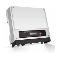
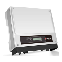
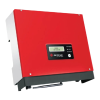
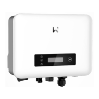
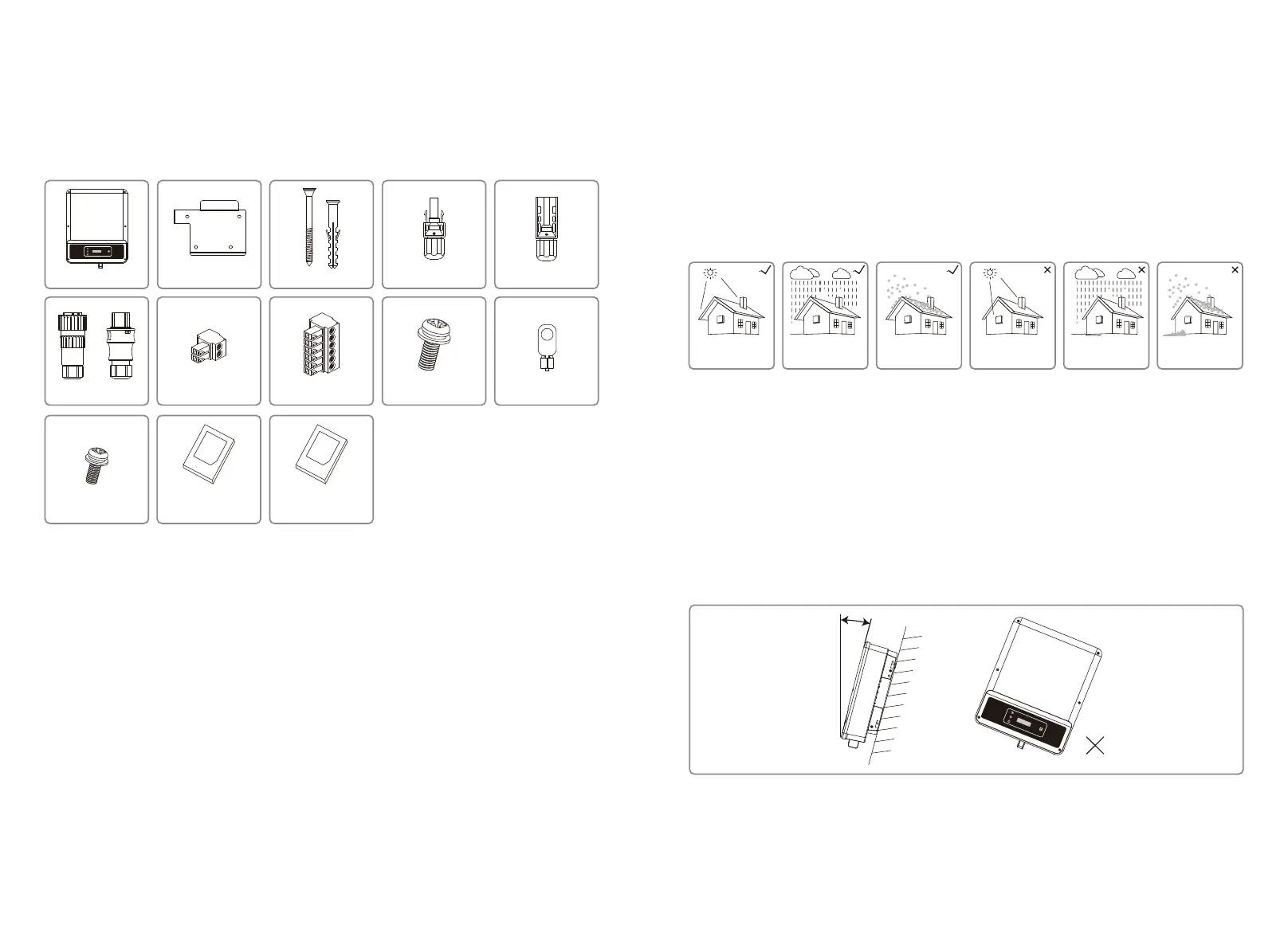
3.2 Package
The unit is thoroughly tested and strictly inspected before delivery. Damage may still occur during
shipping.
1. Check the package for any visible damage upon receiving.
2. Check the inner contents for damage after unpacking.
3. Check the package list below.
Inverter
AC Plug
or
WiFi Configuration
Instruction
Quick Installation
Instruction
Fixed Screw
Fixed Screw 2-Pin Terminal6-Pin Terminal PE Terminal
Positive DC Plug [1] Negative DC Plug [1]Expansion Bolts
05 06
 Loading...