Installation
6 332073C
Installation
Optional Location 1
See F
IG
. 1 on page 5 and F
IG
. 3.
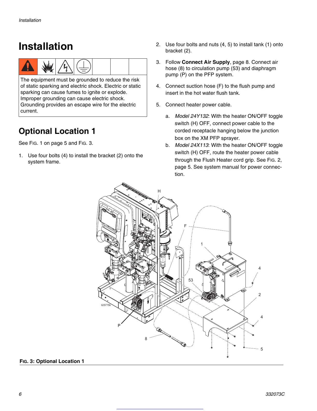
1. Use four bolts (4) to install the bracket (2) onto the
system frame.
2. Use four bolts and nuts (4, 5) to install tank (1) onto
bracket (2).
3. Follow Connect Air Supply, page 8. Connect air
hose (8) to circulation pump (53) and diaphragm
pump (P) on the PFP system.
4. Connect suction hose (F) to the flush pump and
insert in the hot water flush tank.
5. Connect heater power cable.
a. Model 24Y132: With the heater ON/OFF toggle
switch (H) OFF, connect power cable to the
corded receptacle hanging below the junction
box on the XM PFP sprayer.
b. Model 24X113: With the heater ON/OFF toggle
switch (H) OFF, route the heater power cable
through the Flush Heater cord grip. See F
IG
. 2,
page 5. See system manual for power connec-
tion.
The equipment must be grounded to reduce the risk
of static sparking and electric shock. Electric or static
sparking can cause fumes to ignite or explode.
Improper grounding can cause electric shock.
Grounding provides an escape wire for the electric
current.
F
IG
. 3: Optional Location 1
WLE
)
)
+
P
Get other manuals https://www.bkmanuals.com
 Loading...