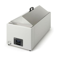
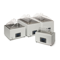
Unstirred water bath SAP, JBA, JBN Service Manual (Version 1.0) September 2013
31667 Page 13 of 23
3.3 Replacing the fuses
The fuses are located on the control and display PCB assembly. To test and replace them,
follow the dismantling instructions in section 2.3 as far as removing the tank. The fuses are
then accessible.
CAUTION: Only replace the fuses if the fault has been fully diagnosed and the fault has
been rectified
WARNING: The fuses must only be replaced by the correct type and rating, see below.
Product safety certification cannot be assumed to be valid if approved fuse type is not fitted.
Model
110-120V units
& 220-230V units
JBA5, JBA12,
JBN5, JBN12,
SAP2, SAP2S, SAP5, SAP12
SAPD
F10AH250V
5 x 20mm, 10A quick blow,
ceramic, 1500A interrupt
rating at 250Vac.
JBA18,
JBN18, JBN26,
SAP18, SAP26, SAP34
F12.5AH250V
5 x 20mm, 12.5A quick
blow, ceramic, 1500A
interrupt rating at 250Vac.
CAUTION: When replacing the fuses take care to avoid distorting the clips. If they do not
grip the fuse tightly there is a risk of overheating and nuisance fuse failures
3.4 Replacing Control and Display PCB
Follow the dismantling instructions in section 2.3 as far as removing the PCB assembly
Fit a correctly configured replacement PCB and reassemble and test the unit following the
instructions in section 4.3
 Loading...