Operation:
The attachment
lift
system of the
tractor
controls
the depth of tilling.
Operation of the
tiller with the engine
at full
throttle
is recommended because maximum
power
is thus pro-
vided.
Engage
the
direction
control lever and then lower thc
tiller. Do
not
DROP tiller into
ground.
Operation
at slow
ground
spceds
gives
a
finer
soil
condition
(srnaller
soil particles).
Select that
gear
rvhich r.vill
produce the
desired
con-
dition,
usually lst
year, lor'v range, however
experimen-
tation may indicate
use
of a slightly
higher
gear
is
acceptable.
Overlap
cuts slightly
to avoid
leaving
ridges of un-
tilled soil.
SAFETY FIRST:
Clear area to be tilled of all trash such as rocks,
large stones,
wire,
bones, etc,
Knclw
the controls and how to
stop tractor and tiller
,-
quickly,
Keep bystanders
away.
Disengage
all
clutches before starting engine.
Disengage all porver
and turn off engine
before
parking, making adjustment,
or clearing trash
(rvire,
vines, etc.)
from
tiller tines,
Use
caution
rvhen
manc.uvering
or transporting.
Keep
tine cover
and
shield in
place.
Stop
and
inspect
tiller for
damage after
striking
Iarge
objects such as
buried stumps or rocks.
Axle
Mount
Attachments
48" Snowdozer
Front-Mount
50" Rotary
Front-Mount 40"
Rotary
Mower
Mower
Figure
28
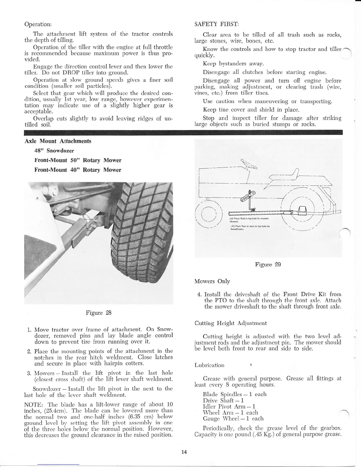
1. Move
tractor over
frame
of
attachment.
On Snow-
dozer,
removed
pins
and
lay
blade
angle
control
dou'n
to
prevent tire from
running over
it.
2, Place
the rnounting
points
of
the attachment
in
the
notches
in the
rear hitch
weldment.
Close latches
and
secure
in
place
rvith
hairpin cotters,
3.
N{orvers
-
Install the
lift
pivot
in
the
last hole
(closest
cross sliaft)
of the
lift lever shaft rveldment.
Snorvdozer
-
Install
the
lift pivot in the next
to the
last hole of the lever shaft
rveldment,
NOTE: The
blade
has
a
lift-lower range of about
10
inches,
(25.4cm).
The
blade can be
lorvered more than
the
norn"ral tu'o and
one-half
inchcs
(6.35
cm) below
ground level b-v setting
the lift
pivot
assembly
in
one
of
the three
holes belolv
the normal
position. Horvever,
this decrcases
the
ground
clearance
in the
raised position.
Lii!
P,vor
qou
rr nP\r
_o
rop
5. e io'
SnowDoze
'.
Figure
29
Mowers
Only
4.
Install
the driveshaft of the
Front Drive Kit
from
the
PTO to the shaft through
the front axle. Attach
the mower driveshaft to the shaft
through front
axle.
Cutting
Height
Adjustment
Cutting
height
is adjusted with
the
two
level ad-
justment
rbds and the
adjustment pin.
The
morver should
be
level
both
front to
rear and
side to
side.
Lubrication
5
Grease u'ith
general purpose.
Grease all
fittings at
least evcry 8 operating
hours.
Blade
Spindles-l each
Drive
Shaft
-
1
Idler
Pivot Arm
-
1
Wheel
Ann-1each
Gauge Wheel-l each
Periodically,
check thc
grease level
of the
gearbox.
Capacity
is
one pound
(,a5
Kg.) of
general
purpose
grease.
L4
 Loading...