EN - 30
3. Adjust Steering Lever Forward or
Backward
1. Loosen, do not remove, the bolts
securing the handlebar to the upper
control arm.
2. Rotate steering lever forward or
backward to desired position and tighten
bolts.
NOTICE: Tighten upper bolt first.
Forward Speed Adjustment
(Figure 23)
The travel of the steering levers may need
adjustment if the unit turns to the right or left
when both steering levers are pushed as far
forward as possible. The unit should track
within 0.6 m (2’) of a straight line for 9.1 m
(30’).
The side the unit turns toward indicates that
the drive wheel on that side is turning slower
than the opposite drive wheel. Either the
wheel that is turning faster needs to slow
down or the wheel that is turning slower
needs to speed up to allow the unit to travel in
a straight line.
IMPORTANT: Check tire pressure before
making adjustments. Incorrect or inconsistent
pressure between tires may cause unit to
track incorrectly.
1. Determine which way the unit turns.
2. Loosen jam nut on the adjustment bolt.
3. Adjust speed by:
• Turning adjustment bolt clockwise to
decrease steering lever travel.
• Turning adjustment bolt
counterclockwise to increase steering
lever travel.
4. Tighten the jam nut.
NOTICE: Reverse speed cannot be adjusted.
If unit tracks excessively left or right in
reverse, see your dealer for repair.
REPLACING PTO BELT
Remove
(Figure 24)
1. Lower mower deck to the ground.
2. Remove belt covers from mower deck.
3. Rotate idler arm clockwise until tension
is removed from PTO belt.
4. Remove PTO belt from left mower deck
pulley.
5. Slowly release idler arm until tension is
removed from idler spring.
6. Remove PTO belt from mower deck and
engine drive pulley.
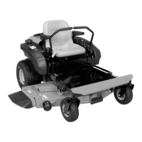
Figure 22
Rotate this end away from the operator
position to move the steering levers out.
Rotate this end away from the operator
position to move the steering levers in.
CAUTION: Use care when
releasing idler spring tension.
Keep body parts well away from
idler when performing this
operation.
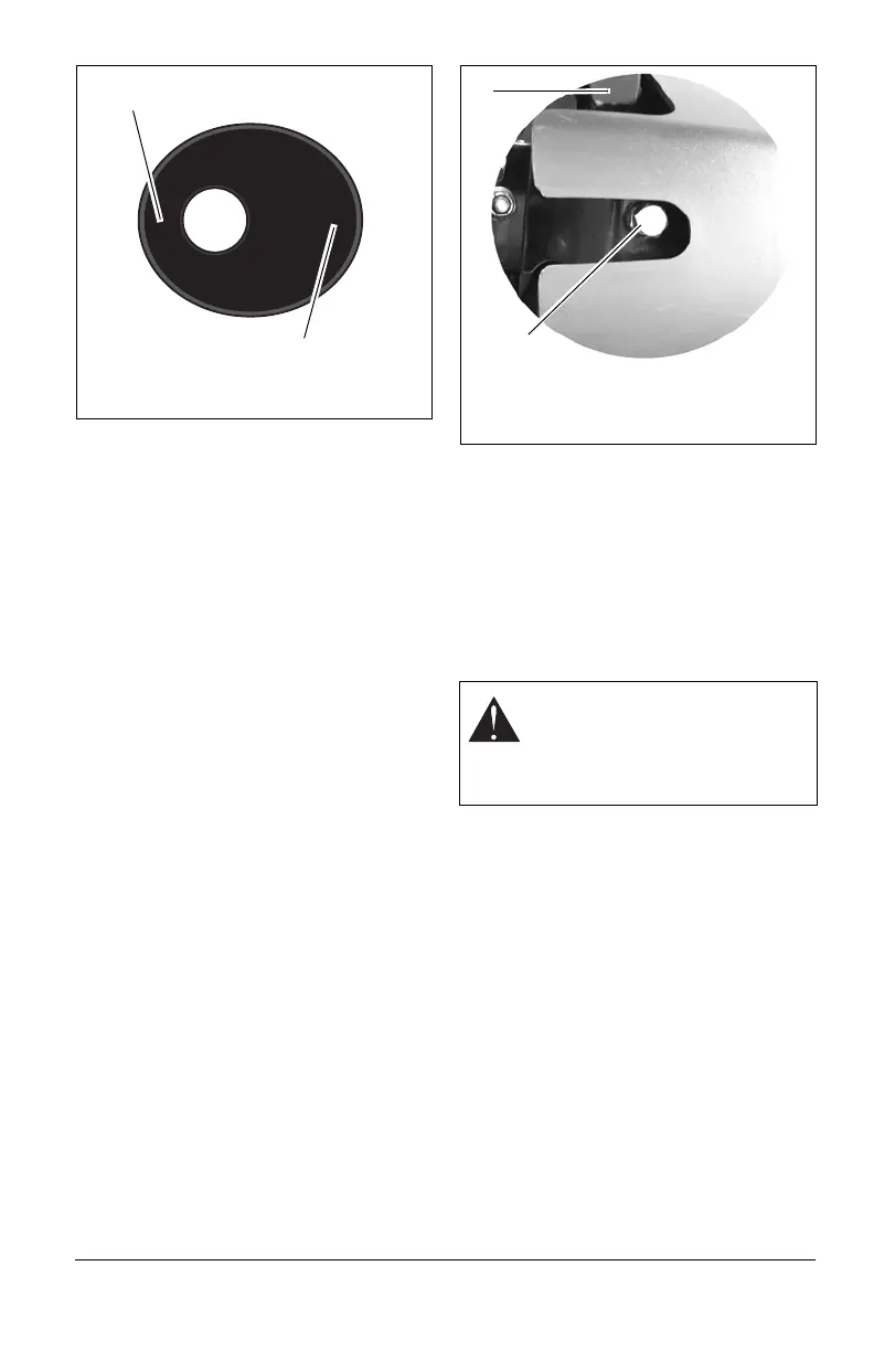
Figure 23
1. Forward Travel Adjustment Bolt
2. Lower Control Arm
1
2
 Loading...