EN - 20
Gravely Dealers will provide any service which
may be required to keep your unit operating at
peak efficiency. Should engine service be
required, it can be obtained from a Gravely
Dealer or the engine manufacturer’s
authorized service center.
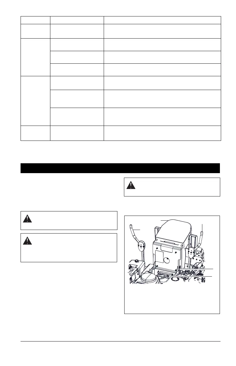
SERVICE POSITION
1. Place unit on a flat level surface.
ALWAYS stop engine. Ensure unit is
secure and will not tip over. Strap and
clamp onto lift if used.
2. Place steering levers in neutral and
engage parking brake.
3. Remove wing knob.
4. Tip seat forward (Figure 5).
5. When service is complete, lower seat
and secure with wing knob or hex nut.
Every
25 Hours
Check Mower Blades Check mower blades for wear. Sharpen or replace as
needed.
See Mower Blades on page 22.
Every
50 Hours
Check Air Filter Check air filter for dirt. Clean as required. Follow
Engine Manual for maintenance schedule.
Lubricate Unit Oil all pivot points and pin connections. Grease lube
fittings. See Lubricate Unit on page 24.
Check Brake Gap Adjust gap if necessary. See Adjusting the Parking
Brake on page 26.
Every
100 Hours
Clean Battery Keep battery and its terminals clean. See Clean
Battery on page 23
.
Check Fasteners Check mower blade mounting hardware and all other
fasteners. Replace missing or damaged fasteners.
Tighten all nuts and bolts to their correct torque value.
Check Belts Replace worn or deteriorated belts. See Replacing
Mower Belts on page 27 and Replacing the Hydro
Pump Belt on page 28.
Every
400 Hours
Change Hydraulic Fluid
and Filter
*
Drain hydraulic fluid tank, replace hydraulic oil filter,
refill system. See Hydraulic Fluid on page 21.
*Change hydraulic fluid and filter after the first 75 hours of operation and then
every 400 hours.
Period Service Task
SERVICE AND ADJUSTMENTS
WARNING: AVOID INJURY. Read
and understand entire Safety section
before proceeding.
CAUTION: HOT SURFACES may
result in injury. DO NOT touch
engine or drive parts which are hot
from operation. Allow parts to cool
before servicing.
CAUTION: Be sure footing is secure
to accomodate weight shift of seat
when rotating it into service position.
1
Figure 5
1. Service Position
2. Steering Levers
3. Parking Brake
4. Battery
2
3
4
2

 Loading...