GMV5 DC INVERTER VRF UNITS SERVICE MANUAL
83
8. Master Unit Setting DIP Switch (SA8_MASTER-S)
The master unit setting DIP switch (SA8_MASTER-S) defines module management of a system. A
master unit must be set, and only one master unit can be set in each refrigerating system (in
power-off status). The setting methods are as follows:
Master Unit Setting DIP Switch
(SA8_MASTER-S)
Upon factory departure, all modules are in ―00‖ master unit status by default. When multiple modules are
connected in parallel, only one module retains the master unit status and other modules are set to
sub-module status. When a module is independently used, it uses the factory settings.
For the basic module set to master unit, the module address is displayed as ―01‖ on the main board.
Precautions:
A. When the DIP switch setting is not covered in the above scope, a DIP switch setting exception fault
may occur.
B. A module must be set to master unit status, and only one module can be set to master unit status in
each refrigerating system. Other modules are set to sub-module status.
C. Settings must be performed in power-off status.
D. The default factory setting is "00" master unit status.
9. DIP Switch Example
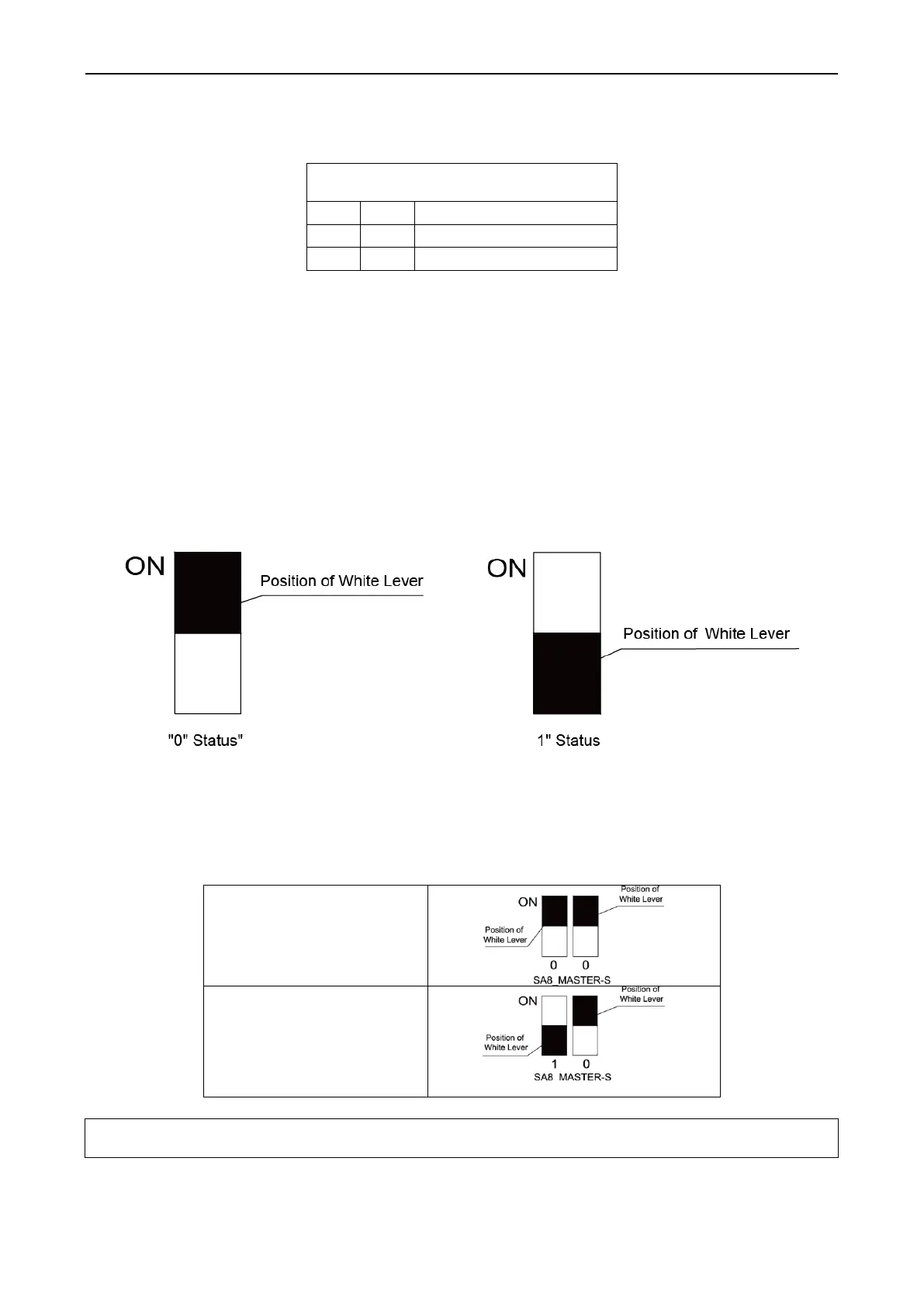
A. Explanation of DIP switch positions
On the DIP switch, ―ON‖ indicates ―0‖ status and the opposite direction indicates "1‖ status.
The position of white lever indicates the position to be set to.
B. Example
The following takes master unit settings as an example. Assume that a system consists of three modules:
module a, module b, and module c. Set module c to master unit and the other two modules to
sub-modules. The settings are as follows:
(II) System Function Button Operations
Module a/Module b (Sub-module)
Note: System function settings and query must be performed after commissioning of the entire unit.
System function settings and query can be used no matter whether the entire unit runs.
1. Introduction to Function Buttons
The main board AP1 of the ODU consists of eight function buttons:
 Loading...


