Home
Gree
Air Conditioner
GMV-80WL/C-T
Gree GMV-80WL/C-T User Manual
4
of 1
of 1 rating
173 pages
Give review
Manual
Specs
To Next Page
To Next Page
To Previous Page
To Previous Page
Loading...
GREE DC
Inverter
Multi
VRF
System
II
Service
Manual
8
4.2 Operation range
Cooling Outdoor
temperature:
-5
ć
52
ć
Heating Outdoor
temperature:
-20
ć
27
ć
5 Product Cap
acity Correction
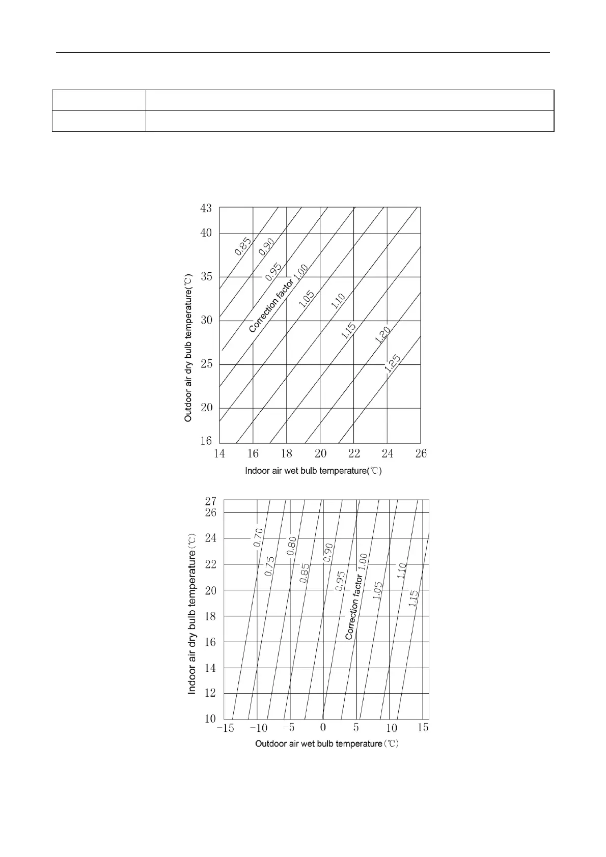
5.1Correction factor of indoor and out
door temperature
1
˅
˅
Correction factor of cooling capacity
2
˅
Correction factor of heating capacity
11
13
Table of Contents
Default Chapter
2
Table of Contents
2
Product List
5
Nomenclature of Outdoor Units
7
Product Features
7
General Introduction
7
Specifications
8
Intelligent PID Capacity Regulation
8
Complete Protection
8
Operation Range
12
Product Capacity Correction
12
Correction Factor of Indoor and Outdoor Temperature
12
Correction Factor of Pipe Length and Height Difference
13
Symbol Description
13
Principal of Operation
14
Units' Control
19
Schematic Diagram of Units' Control
19
Interpretation on the Schematic Diagram
19
Remote Monitoring System
19
General Introduction
19
Monitoring Software
20
Function Introduction
20
Connection of Computer and Units
20
Parts Introduction
21
List of Parts
21
Gree USB Data Converter
21
Functions Introduction
21
Operation Instruction
22
Installation Notice
23
Communication Board
23
Communication Cord
23
USB Wire
23
Software Introduction
24
One-Button Commissioning
24
Comprehensive Monitoring
24
Real-Time Control
24
Software Installation
25
Installation Requirements
25
Computer Configuration
25
CD Playing
25
Installation Flowchart
26
Button Graphics
26
Installation Process
26
Install .Net Framework 4.0
26
Extracting Files
27
Install Gree USB Data Converter
36
Project Debugging
46
Other Functions
51
Capture Screen
51
Search for Database Folder
52
Usage of USB Converter
55
Usage of Converter
55
Usage of Converter Configuring Software
60
Ex-Factory Defaulted Baud Rate: (Unit: Bps)
60
Baud Rate Look-Up Table for RS485 Interface (Unit: Bps)
60
Baud Rate Look-Up Table for HBS Interface (Unit: Bps)
61
Baud Rate Look-Up Table of CAN Interface (Unit: Bps)
61
Engineering Installation Preparation and Notice
65
Installation Key Points and Importance
65
Installation Materials Selection
66
Refrigerant Piping
66
Material Requirement
66
Appearance Requirement
66
Condensate Water Pipe
67
Insulation Material
67
Communication Cable and Control Cable
67
Power Cable
68
Hanger Rod and Support
68
Installation of Outdoor Unit
68
Check before Installation
68
Selection of Installation Site
68
Carrying and Installing Outdoor Unit
68
Installation Notices
69
Fixing and Damping of Unit
69
Outline Dimension and Position of Installation Hole
69
Installation Space Requirement
71
Debugging &Maintenance
72
Debugging of Unit
73
Preparation for Debugging
73
Stage Process Instruction for Debugging
74
Debugging of Unit
74
Parameters Reference Value for the Normal Operation of Unit
79
Malfunction List for the Wired Controller
81
Status Display Table for Indicators on Main Board of Outdoor Unit
82
Function Setting of Outdoor Unit
83
ODU Quiet Function
84
Cool & Heat Function
85
Mode Lock Control
85
Forced Defrosting
86
Restore Factory Defaults
86
Static Pressure Function
86
Troubleshooting
92
Troubleshooting Principle
92
Communication Malfunction
92
High Pressure Protection
93
Low-Pressure Protection
94
Discharge Temperature Protection
95
Mafunction of Temperature Sensor
96
Malfunction of Sensor
96
Unit and Main Board Can’t be Energized
96
Failure Start-Up
97
Drive IPM Overtemperature Protection for Compressor
97
Desynchronizing Protection for Inverter Compressor
98
Failure Startup for Inverter Compressor
98
Loop Malfunction of Driven Charging for Compressor
99
Malfunction of Memory Chip for Inverter Compressor
99
Overcurrent Protection for Inverter Compressor
100
IPM Module Protection
100
High Pressure Protection for Driven DC Bus Bar of Compressor
100
AC Current Protection for Inverter Compressor
101
Power Distribution of Unit
102
Main Electric Parts
102
Circuit Diagram
103
Circuit Diagram of Outdoor Unit
103
Gmv-141Wl/C-T
104
Gmv-120Wl/A-T, Gmv-140Wl/A-T, Gmv-160Wl/A-T
104
Removal of Parts
108
Key Parts
108
Removal of Key Parts
110
Removal Operation for Panel
110
Removal Operation for Blade
111
Removal Operation of Compressor
113
Removal Operation for 4-Way Valve
117
Remival Operation for Eletronic Expansion Valve
117
Removal Operation of Gas Liquid Separator
118
Removal Operation for Plate Heat Exchanger
119
Common Maintenance
144
Vacuum Drying for the System
144
Selection Requirement for the Vaccum Pump
144
Operation Procedure and Notices for Vacuum Drying
144
Fill and Charge Refrigerant
145
Filling Procedure of Regrigerant
145
Calculation Example
145
Total Length of each Liquid Pipe
146
Calculation of the Amount of Additional Refrigerant
146
Airtightness Test
149
Importance of Airtightness Test
149
Operation Procedure for the Airtightness Test
149
Cautions
149
Exploed View for Outdoor Unit and Parts' List
150
Gmv-140Wl/C-X Gmv-160Wl/C-X
165
Gmv-H224Wl/A-X
167
Gmv-H280Wl/A-X
169
Gmv-H280Wl/A-X
170
Gmv-H335Wl/A-X
171
Gmv-335Wl/C-X
171
4
Based on 1 rating
Ask a question
Give review
Questions and Answers:
Need help?
Do you have a question about the Gree GMV-80WL/C-T and is the answer not in the manual?
Ask a question
Gree GMV-80WL/C-T Specifications
General
Brand
Gree
Model
GMV-80WL/C-T
Category
Air Conditioner
Language
English
Related product manuals
Gree GMV-80WL/A-T
173 pages
Gree GMV series
69 pages
Gree GMV-R series
188 pages
Gree GMV-60WL/C-T
36 pages
Gree GMV-121WL/C-T
173 pages
Gree GMV-ND63T/A-T
53 pages
Gree GMV-140WL/C-X
173 pages
Gree GMV-ND28C/A-T
30 pages
Gree GMV-160WL/C-T
173 pages
Gree GMV-ND22T/B-T
24 pages
Gree GMV-120WL/C-X
173 pages
Gree GMV-ND56T/B-T
24 pages
 Loading...
