GREE DC Inverter Multi VRF System II Service Manual
75
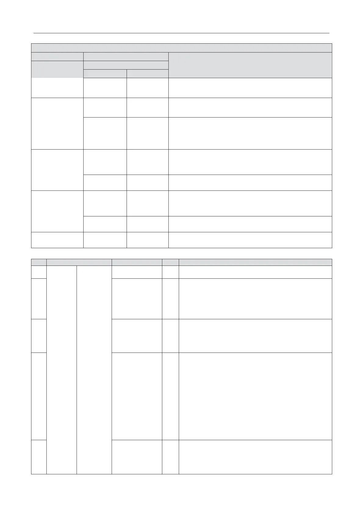
Description of each stage of debugging progress
Code meaning and operation method
Progress
10/oC
Valves status is normal. Unit will display as in the left for 2s and
then start next step.
12_ Confirm
debugging startup
12/AP
Ready for units to start debugging. Press main board’s SW3
button to confirm
startup of debugging. 2s later, main board will
display as below:
12/AE
Startup is confirmed. After displaying for 2s, system will choose
“15_Cooling debugging” or “16_Heating debugging” according to
ambient temperature. If the project requests to add refrigerant
but it is not complemented before debugging, then refrigerant
can be added in this process through the L-VALVE.
debugging
15/AC
Debugging for cooling mode. If no malfunction occurs for 50min
when compressor is running, then the system is certified as
normal. After shutting down the unit for 5s, the system will enter
normal standby status.
Malfunction occurs when debugging for cooling mode.
16_ Heating
debugging(For
heat pump units
only)
16/AH
Debugging for heating mode. If no malfunction occurs for 50min
when compressor is running, then the system is certified as
normal. After shutting down the unit for 5s, the system will enter
normal standby status.
Malfunction occurs when debugging for heating mode.
oF ON
The entire unit has finished debugging and under standby-by
condition.
1.3 Parameters reference value for the normal operation of unit
unit
Outdoor ambient
temperature
ć
Discharge
temperature of
compressor
ć
●After compressor is started up, normal discharge
temperature for cooling is 70~105
ć, which is 10ć
above
more than the high pressure saturation temperature.
●The normal temperature for heating is 65
ć~90ć, whi
ć above more than the high pressure saturation
temperature
ć
●During cooling operation, defrosting temperature is 4~10ć
lower than the high pressure value of system;
●During heating operation, defrosting temperature is almost
equal to the low pressure value of system (the disffrence is
withing 2ć).
system
ć
●Under cooling mode, the normal high pressure value is
20
ć55ć. According to the change of ambine
temperature and operation capacity of system,
the high
pressure value of system is 10
ć30ć higher than the
ambient temperature. The higher the ambient temperature,
the temperature difference is small; Under cooling operation
at the ambient temperature of 25~35
ć
, the high pressure
value for the system
is 44~53ć;
●The unit will operate at heating mode when the ambient
temperature is above
-5ć
. The high pressure value for the
system is 40~52
ć
. When the ambient temperature is low
and the indoor unit is started up frequently, the high pressure
value will be a little lower.
system
ć
●The unit will operate under cooling mode when the ambient
temperature is 25~35
ć, the low pressure value for the
ć.
●The unit will operate under heating mode when the
ambient temperature is above -5ć, the low pressure value
 Loading...
