GMV DC Inverter VRF
35
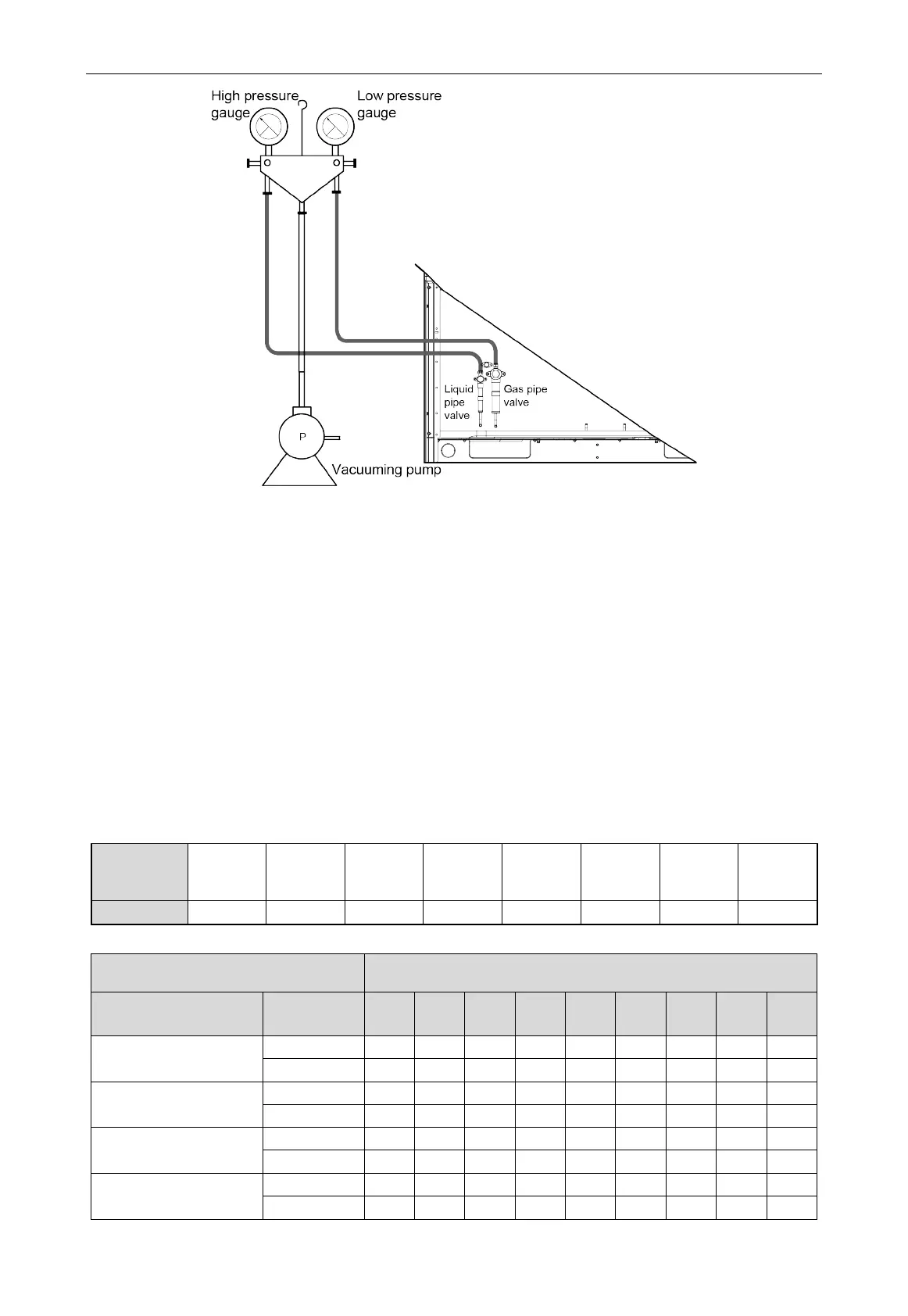
Fig.3.6.2
2) When the vacuum pump is turned off to stop vacuuming, the valve should be closed at
first and then cut off the power for the vacuum pump.
3) Keep the vacuum for 2 hours and confirm that the pressure of the vacuum gauge has not
risen.
3.7 Additional Refrigerant Charging
3.7.1 Calculation Method of Adding Refrigerant
Total refrigerant charging amount R= Pipeline charging amount A + ∑charging amount B of every
module.
(1) Pipeline charging amount:
Pipeline charging amount A= ∑Liquid pipe length × refrigerant charging amount of every 1m liquid
pipe.
Diameter of
liquid pipe
Φ28.6 Φ25.4 Φ22.2 Φ19.05 Φ15.9 Φ12.7 Φ9.52 Φ6.35
(2) Σ Refrigerant charging amount B of every module
Refrigerant charging amount B of every
②
Module capacity(kW)
IDU/ODU rated capacity
collocation ratio C
①
Quantity of
indoor unit
22.4 28 33.5 40 45 50.4 56 61.5 68
50%≤C≤70%
70%
<
C≤90%
≥4 1 1 1 2 2 2.5 3 3.5 3.5
90%
<
C≤105%
105%
<
C≤135%
 Loading...
