GREE GMV5E DC INVERTER VRF UNITS SERVICE MANUAL
15
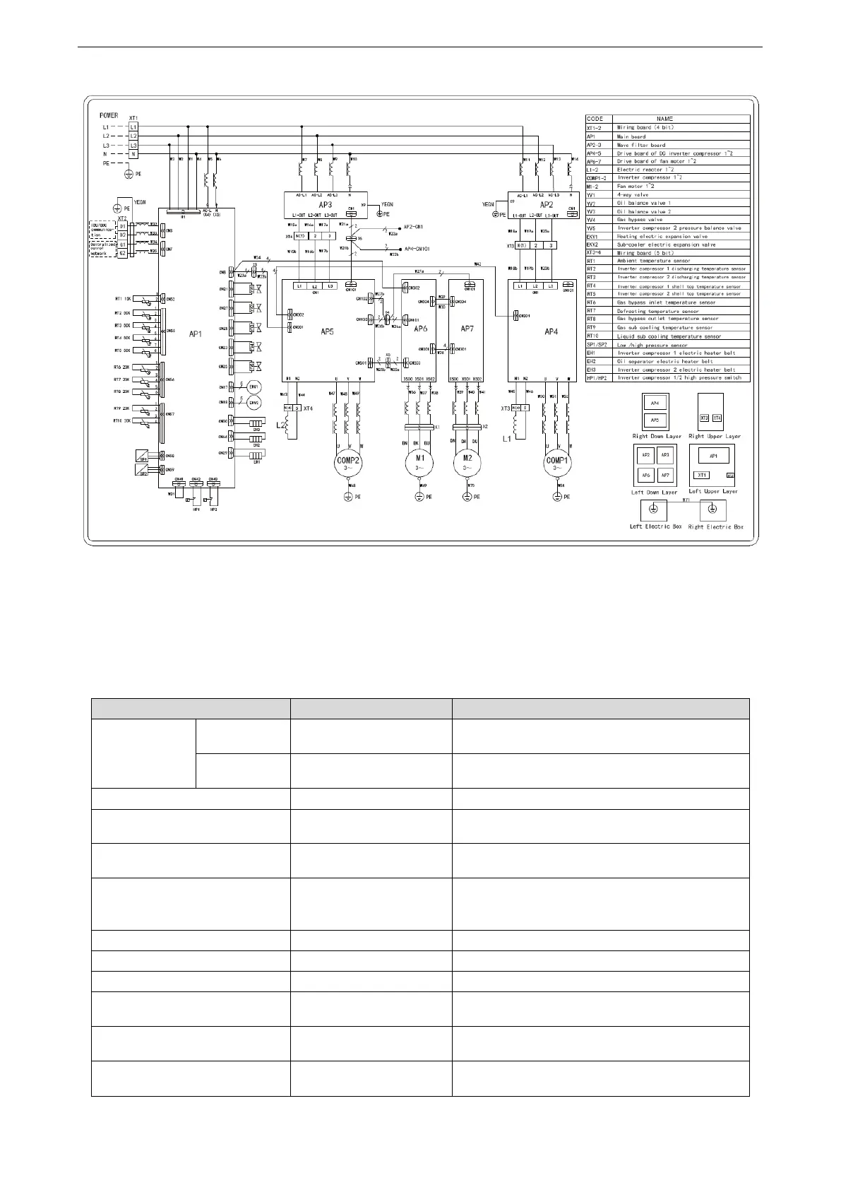
Circuit diagram of GMV-450WM/E-X, GMV-504WM/E-X, GMV-560WM/E-X and GMV-615WM/E-X
NOTE:
This drawing is just for reference; please always refer to the electric wiring stuck to the unit for
actual wiring.
1.6 Optional Accessories
GMV5E series VRF units support the following optional accessories:
For the model selection method, see the part of
pipeline selection.
FQ01A/A, FQ01B/A,
FQ02/A, FQ03/A, FQ04/A
Remote receiving LED panel
Applicable to the air duct-type indoor unit
Dct-type indoor unit Otional (Wall-Mounted indoor
unit Standard)
Remote controller for debugging
With the debugging function, used to set functions
of the indoor unit
Applicable to the air Cassette, Floor Ceiling,
Wall-Mounted indoor unit Otional (duct-type indoor
unit Standard)
With the access control function
Colour screen wired controller
Applicable to the unit of CAN bus communication
technology
Applicable to the unit of CAN bus communication
technology
Applicable to the unit of CAN bus communication
technology

 Loading...