119
GMV6 DC Inverter VRF Units Technical Sales Guide
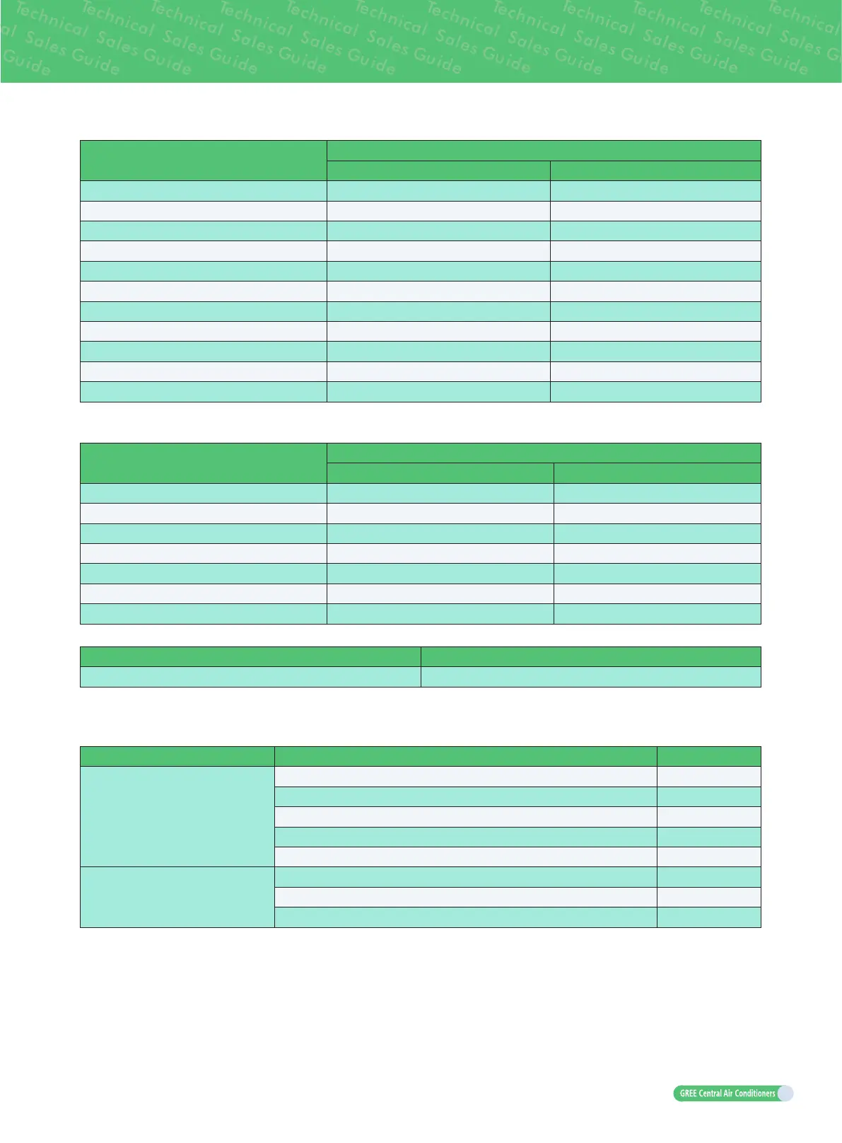
Total rated capacity X (kW) of downstream IDU
Piping size of indoor branches
Gas pipe (mm) Liquid pipe (mm)
X≤5.0
Φ
12.7
Φ
6.35
5.0<X≤14.2
Φ
15.9
Φ
9.52
14.2<X≤22.4
Φ
19.05
Φ
9.52
22.4<X≤30.0
Φ
22.2
Φ
9.52
30.0<X≤40.0
Φ
25.4
Φ
12.7
40.0<X≤45.0
Φ
28.6
Φ
12.7
45.0<X≤68.0
Φ
28.6
Φ
15.9
68.0<X≤96.0
Φ
31.8
Φ
19.05
96.0<X≤135.0
Φ
38.1
Φ
19.05
135.0<X≤186.0
Φ
41.3
Φ
19.05
186.0<X
Φ
44.5
Φ
22.2
(5) Fitting pipe "E" between indoor unit and manifold.
Manifold should be matched with fitting pipe of indoor unit.
Rated capacity C (kW) of IDU
Piping size of indoor branch and IDU
Gas pipe (mm) Liquid pipe (mm)
C≤2.8
Φ
9.52
Φ
6.35
2.8<C≤5.0
Φ
12.7
Φ
6.35
5.0<C≤14.2
Φ
15.9
Φ
9.52
14.2<C≤22.4
Φ
19.05
Φ
9.52
22.4<C≤30.0
Φ
22.2
Φ
9.52
30.0<C≤40.0
Φ
25.4
Φ
12.7
40.0<C≤45.0
Φ
28.6
Φ
12.7
(6) Select the branch “
①
” of outdoor module.
- Model
Selection of outdoor modular branch ML01/A
(7) Select the manifold “
②
” at indoor side.
Manifold at indoor unit side can be selected as per total capacity of downstream indoor unit(s). Refer to
the following table.
R410A refrigerant system Total rated capacity of downstream IDU X (kW) Model
Y-shape branch
X<20.0 FQ01A/A
20.0≤X≤30.0 FQ01B/A
30.0<X≤70.0 FQ02/A
70.0<X≤135.0 FQ03/A
135.0<X FQ04/A
T-shape branch
X≤40.0 FQ14/H1
X≤68.0 FQ18/H1
68.0
<
X FQ18/H2
 Loading...


