127
GMV6 DC Inverter VRF Units Technical Sales Guide
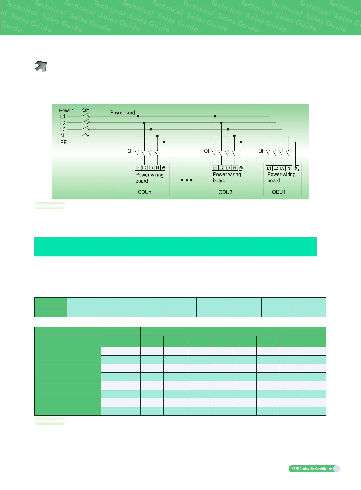
10.2 External wiring
Each unit should be equipped with a circuit breaker for short circuit and abnormal overload protection.
The circuit breaker is normally closed. During operation, all ODUs and IDUs in the same system must
be energized status; otherwise, the system cannot work normally.
NOTES:
a. The maximum outdoor unit quantity “n” is decided by the combination from of outdoor unit.
b. Please refer to the actual requirement of unit for the earthing position.
11
CALCULATION METHOD ON ADDING QUANTITY OF PIPING REFRIGERANT
Total refrigerant charging amount R= Pipeline charging amount A + ∑charging amount B of every
module.
(1) Pipeline charging amount:
Pipeline charging amount A= ∑Liquid pipe length × refrigerant charging amount of every 1m liquid
pipe.
Liquid pipe
diameter(mm)
Φ
28.6
Φ
25.4
Φ
22.2
Φ
19.05
Φ
15.9
Φ
12.7
Φ
9.52
Φ
6.35
kg/m 0.680 0.520 0.350 0.250 0.170 0.110 0.054 0.022
(2) Σ
Refrigerant charging amount B of every module:
Adding quantity of ODU refrigerant B(kg)** ODU capacity(kW)
Allocation rate of rated
capacity of IDU and ODU C*
Allocation
quantity of IDU
22.4 28 33.5 40 45 50.4 56 61.5
50%≤C≤70%
<4 0 0 0 0 0 0 0 0
≥4 0.5 1 1 1 1 0.5 1 1.5
70%<C≤90%
<4 0.5 1 1 2 2 1.5 2 2
≥4 1 1 1 2 2 2.5 3 3.5
90%<C≤105%
<4 1 1 1 2 2 2.5 3 3.5
≥4 2 2 2 4 4 4 5 5
105%<C≤135%
<4 2 2 2 3 3 3.5 4 4
≥4 3.5 4 4 5 5 5.5 6 6
NOTES:
a.*Rated capacity configuration rate of indoor unit and outdoor unit C = sum of indoor unit rated
cooling capacity / sum of outdoor unit rated cooling capacity.
b.**If all indoor units are all fresh air indoor units, the added refrigerant amount for each module B is
0kg.
 Loading...


