21
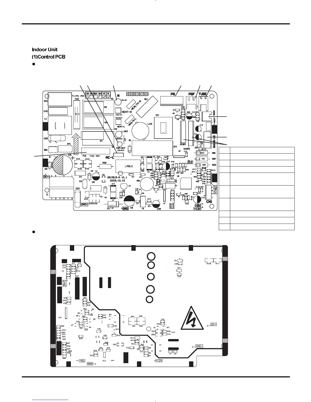
5.3 Printed Circuit Board
TOP VIEW
BOTTOM VIEW
Schematic Diagram
12 3 4 5 6
7
8
9
10
1 Interface of input live wire
2 Interface of communication wire
3 Interface of input neutral wire
4 PG motor control interface
5 Feedback interface from PF
motor
6 Interface of pipe temperature
sensor
7 Interface of ambient temperature
sensor
8 Interface of air guide motor
9 Display interface
10 Protective tube

 Loading...