9
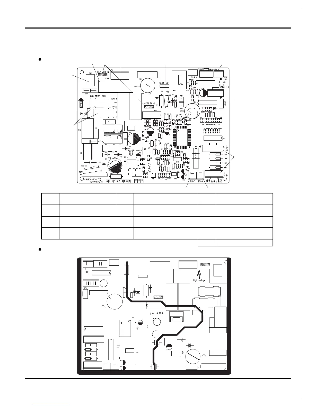
5.3 Printed Circuit Board
Schematic Diagram
BOTTOM VIEW
For 07/09/12K Unit
TOP VIEW
1
2
354678
9
10
1112
13
1
Power supply live wire
connector
5 Indoor fan wire terminal 9 Jumper cap terminal
2
Power supply neutral wire
connector
6
indoor and outdoor unit
communication wire terminal
10 Display panel terminal
3 Fan capacitor 7
Up & down swing control
terminal
11
Indoor ambient temperature
sensor
4
Health function
terminal(optional)
8 Indoor fan feedback terminal 12
Indoor pipe temperature
sensor
13 Protective tube