13
Technical Information
Service Manual
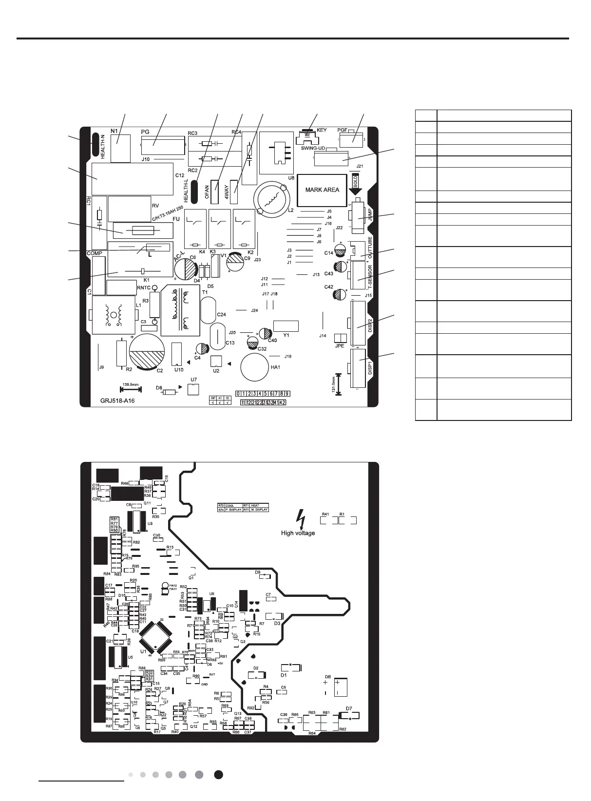
5.2 PCB Printed Diagram
● Top view
● Bottom view
1
2
3
4
5
67
89
10
11 12
13
14
15
16
No. Name
1 Wiring terminal of compressor
2 Terminal of live wire
3 Fuse
4 Fan capacitor
5
Neutral wire terminal of cold
plasma
6 Terminal of neutral wire
7 Wiring terminal of PG motor
8 Live wire terminal for cold plasma
9
Wiring terminal of outdoor fan
(heat pump unit)
10
Wiring terminal of 4-way valve
(heat pump unit)
11 Auto button
12
Feedback wiring terminal of PG
motor
13
Wiring terminal of up&down swing
motor
14 Jumper cap
15
Wiring terminal of outer tube
temperature sensor
16
Wiring terminal of indoor unit
temperature sensor
17
Wiring terminal 2 for display
receiving board
18
Wiring terminal 1 of display
receiving board
 Loading...