Loading...
Do you have a question about the Gree GWH09AAA-K3NNA1A and is the answer not in the manual?
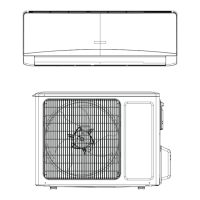
| Cooling Capacity | 9000 BTU/h |
|---|---|
| Power Supply | 220-240V, 50Hz |
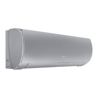
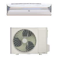
| Type | Split System |
| Outdoor Unit Noise Level | 50 dB |
| Operating Temperature Range (Cooling) | 18°C to 43°C |