34
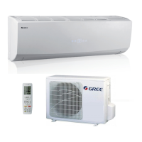
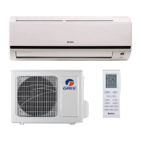
Installation and Maintenance
Service Manual
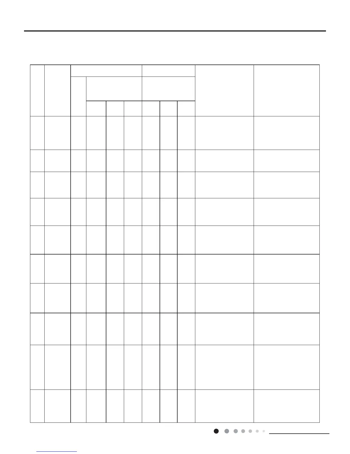
9.1 Flashing LED of Indoor/Outdoor Unit and Primary Judgement
No.
0DOIXQFWLRQ
Name
'LVSOD\0HWKRGRI,QGRRU8QLW
'LVSOD\0HWKRGRI2XWGRRU
Unit
$&VWDWXV 3RVVLEOH&DXVHV
'XDO
Code
Display
,QGLFDWRU'LVSOD\GXULQJ
EOLQNLQJ21VDQG2))
0.5s)
,QGLFDWRUKDVNLQGVRI
GLVSOD\VWDWXVDQGGXULQJ
EOLQNLQJ21VDQG2))
0.5s
Operation
Indicator
Cool
Indicator
Heating
Indicator
Yellow
Indicator
Red
Indicator
Green
Indicator
1
+LJK
SUHVVXUH
protection of
system
E1
'XULQJFRROLQJDQGGU\LQJ
operation, except indoor
fan operates, all loads stop
operation.
'XULQJKHDWLQJRSHUDWLRQWKH
FRPSOHWHXQLWVWRSV
3RVVLEOHUHDVRQV
5HIULJHUDQWZDVVXSHUDEXQGDQW
3RRUKHDWH[FKDQJHLQFOXGLQJ
¿OWKEORFNDJHRIKHDWH[FKDQJHU
DQGEDGUDGLDWLQJHQYLURQPHQW
$PELHQWWHPSHUDWXUHLVWRRKLJK
2
Antifreezing
protection
E2
OFF 3S
DQGEOLQN
3 times
'XULQJFRROLQJDQGGU\LQJ
operation, compressor and
RXWGRRUIDQVWRSZKLOHLQGRRU
fan operates.
3RRUDLUUHWXUQLQLQGRRUXQLW
)DQVSHHGLVDEQRUPDO
(YDSRUDWRULVGLUW\
3
6\VWHPEORFN
or refrigerant
OHDNDJH
E3
OFF 3S
and
EOLQN
9 times
7KH'XDO&RGH'LVSOD\ZLOO
VKRZ(XQWLOWKHORZSUHVVXUH
VZLWFKVWRSRSHUDWLRQ
/RZSUHVVXUHSURWHFWLRQ
/RZSUHVVXUHSURWHFWLRQRI
system
/RZSUHVVXUHSURWHFWLRQRI
compressor
4
+LJK
GLVFKDUJH
WHPSHUDWXUH
protection of
compressor
E4
OFF 3S
DQGEOLQN
7 times
'XULQJFRROLQJDQGGU\LQJ
operation, compressor and
RXWGRRUIDQVWRSZKLOHLQGRRU
IDQRSHUDWHV'XULQJKHDWLQJ
operation, all loads stop.
3OHDVHUHIHUWRWKHPDOIXQFWLRQ
DQDO\VLVGLVFKDUJHSURWHFWLRQ
RYHUORDG
5
2YHUFXUUHQW
protection
E5
OFF 3S
DQGEOLQN
5 times
'XULQJFRROLQJDQGGU\LQJ
operation, compressor and
RXWGRRUIDQVWRSZKLOHLQGRRU
IDQRSHUDWHV'XULQJKHDWLQJ
operation, all loads stop.
6XSSO\YROWDJHLVXQVWDEOH
6XSSO\YROWDJHLVWRRORZDQG
ORDGLVWRRKLJK
(YDSRUDWRULVGLUW\
6
&RPPXQL
cation
0DOIXQFWLRQ
E6 OFF
'XULQJFRROLQJRSHUDWLRQ
FRPSUHVVRUVWRSVZKLOH
indoor fan motor operates.
'XULQJKHDWLQJRSHUDWLRQWKH
FRPSOHWHXQLWVWRSV
5HIHUWRWKHFRUUHVSRQGLQJ
PDOIXQFWLRQDQDO\VLV
7
+LJK
WHPSHUDWXUH
resistant
protection
E8
OFF 3S
DQGEOLQN
6 times
'XULQJFRROLQJRSHUDWLRQ
FRPSUHVVRUZLOOVWRSZKLOH
indoor fan will operate.
'XULQJKHDWLQJRSHUDWLRQWKH
FRPSOHWHXQLWVWRSV
5HIHUWRWKHPDOIXQFWLRQDQDO\VLV
RYHUORDGKLJKWHPSHUDWXUH
resistant).
8
EEPROM
PDOIXQFWLRQ
EE
OFF 3S
DQGEOLQN
11 times
'XULQJFRROLQJDQGGU\LQJ
operation, compressor will stop
ZKLOHLQGRRUIDQZLOORSHUDWH
'XULQJKHDWLQJRSHUDWLRQWKH
FRPSOHWHXQLWZLOOVWRS
5HSODFHRXWGRRUFRQWUROSDQHO$3
9
/LPLW
decrease
IUHTXHQF\
GXHWRKLJK
WHPSHUDWXUH
RIPRGXOH
EU
All loads operate normally,
ZKLOH
RSHUDWLRQIUHTXHQF\IRU
compressor is decreased
'LVFKDUJLQJDIWHUWKHFRPSOHWHXQLW
LVGHHQHUJL]HGIRUPLQVFKHFN
ZKHWKHUWKHWKHUPDOJUHDVHRQ
,300RGXOHRIRXWGRRUFRQWURO
SDQHO$3LVVXI¿FLHQWDQGZKHWKHU
WKHUDGLDWRULVLQVHUWHGWLJKWO\
,ILWVQRXVHSOHDVHUHSODFHFRQWURO
panel AP1.
10
0DOIXQFWLRQ
protection of
MXPSHUFDS
C5
:LUHOHVVUHPRWHUHFHLYHUDQG
EXWWRQDUHHIIHFWLYHEXWFDQ
QRWGLVSRVHWKHUHODWHG
command
1RMXPSHUFDSLQVHUWRQ
PDLQERDUG
,QFRUUHFWLQVHUWRIMXPSHUFDS
-XPSHUFDSGDPDJHG
$EQRUPDOGHWHFWLQJFLUFXLWRI
PDLQERDUG
9. Maintenance
 Loading...