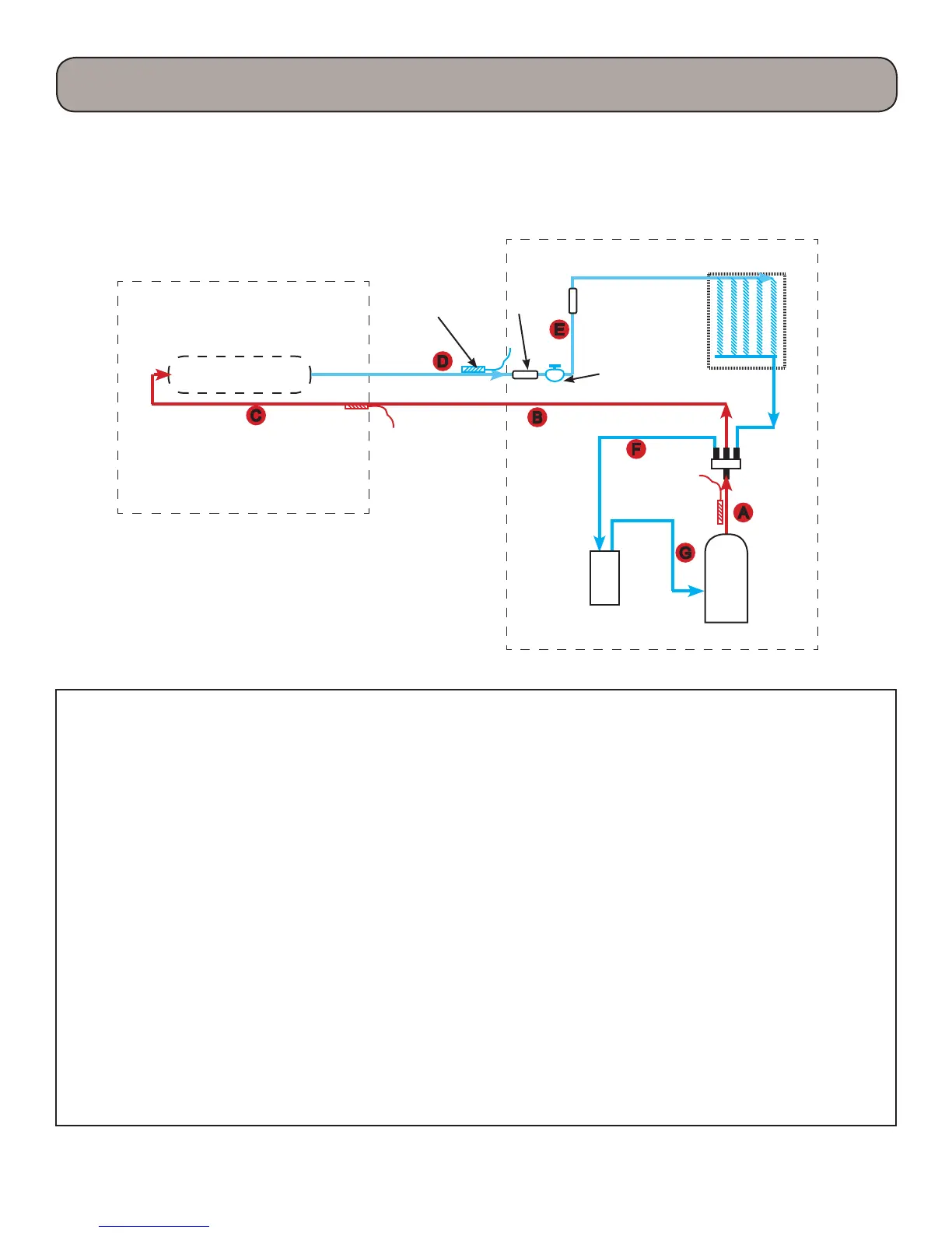
10
Indoor Unit
Outdoor Unit
Heat Exchanger
Heat
Exchanger
Inverter
Compressor
Accumulator not
on all sizes
4-way
valve
Electronic
expansion
valve
Filter
Heating Mode
A. Hot gas is discharged from the compressor. e temperature of the gas in monitored by the Discharge Tem-
perature sensor and sent to the outdoor control panel.
B. e hot gas is directed through the 4-way valve to the indoor coil making the line a hot gas line.
C. e hot gas will enter the indoor coil and condense to a saturated mix as it travel through the coil and will be
slightly subcooled.
D. e refrigerant returns to the outdoor unit through the lter, then trough the EEV reducing the refrigerant
to a low pressure liquid and will maintain 10 degrees F of superheat.
E. e cold refrigerant will travel through the outdoor coil (evaporator) and will pickup heat from the outdoor
air. is will cause the cold saturated refrigerant to ash to a saturated mixture which will be superheated to
10 degrees F.
F. e superheated vapor will travel through the 4-way valve to the accumulator which will prevent liquid
oodback.
G. e superheated gas will enter the compressor for another refrigeration cycle.
e control board will monitor the temperature and pressures and adjust the frequency of the compressor and
ow rate of the EEV as needed. ere are no pressure charts to evaluate temperature or pressures.
Temperature
Sensor
Product Introduction
 Loading...