HVLS Touchscreen Control 5
If one control will be used to operate multiple fans,
verify that the following fan networking steps have been
completed prior to control start-up. Otherwise, continue
on to the Operation section.
Daisy-Chain Communication Wiring
For proper network communication, HVLS fans must be
daisy-chained together using the following instructions.
NOTE: All communication wiring must be installed
in compliance with NEC 800-52 or similar. All
communication wiring needs a minimum separation of
2 inches from high voltage unless installed in separate
raceways/conduit. When possible, maintain 24 inch of
separation.
1. Connect the first HVLS fan in the daisy-chain to
the control using the shielded, twisted pair CAT-
5e communication cable that was provided with
the HVLS fan. CAT-5e cable can be plugged into
any open receptacle on the shielded RJ45 splitter
located at the top of the fan’s downtube.
IMPORTANT: Touchscreen controls, temperature/
humidity sensors, and HVLS fans must be installed with
the supplied CAT-5e communication cable or shielded,
twisted pair CAT-5e (by others) that complies with the
following specifications. Cable must be twisted pair,
shielded 26 ga. CAT-5e cable with a drain wire and must
be compliant with ISO 11801. Cable must use shielded
RJ45 connectors with a soldered drain and wiring
configuration must follow EIA/TIA T568B wiring pinout.
Individual CAT-5e cable lengths must not exceed 200 ft.
in order to prevent network communication issues.
2. Plug an additional shielded, twisted pair CAT-5e
control cable into the shielded 2-way RJ45 splitter
located at the top of the downtube on the first fan.
Connect the other end of this CAT-5e cable into the
2-way splitter on the next fan.
3. Repeat step 2 for subsequent fans until all fans
in the chain are connected in series, as shown in
Figure 2.
FAN 1
CONTROL
FAN 2
Figure 2
Fan Networking
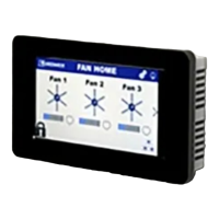
For proper network communication, the dipswitch
settings and wiring on each fan’s variable frequency
drive circuit board may need to be adjusted using the
following instructions.
DIPSWITCH 3
DIPSWITCH 2
First Fan
FIRST FAN IN SERIES
ALL OTHER FANS IN SERIES
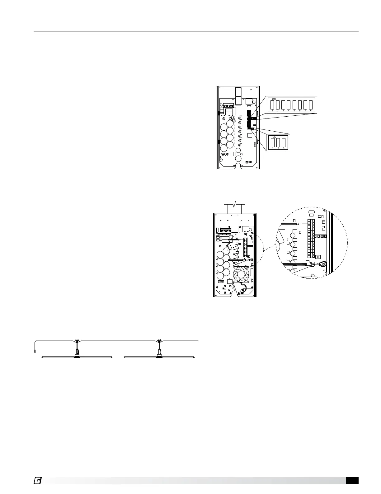
1. Determine the first fan in the network daisy-chain
by identifying the fan that is connected directly to
the control source.
2. Remove the front VFD cover from the first fan in the
network using a phillips screwdriver.
3. On the communication wiring terminal strip,
remove the 24V (brown-white) wire and cap with
a wire nut or heat shrink. Additionally, remove the
stranded silver drain wire that is attached to the
circuit board mounting screw and isolate from all
circuit board components using heat shrink.
4. Dipswitch 2 is used to set parameters that improve
network function. Verify that each of the switches
on dipswitch 2 are set as follows:
Position 1 – Off
Position 2 – On
Position 3 – On
5. Verify that each of the switches on dipswitch 3 are
set as follows. Positions 1 – 5 are used to set the
Pre-Start-Up Checks
 Loading...