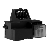
Contact PWM LIN Cable
1 PWM input VBAT Brown
2 Signal reference Signal reference Blue
3 PWM output LIN bus signal Black
TM079641
Control box without signal connection
TM079642
Control box with Mini SS connection
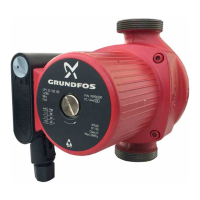
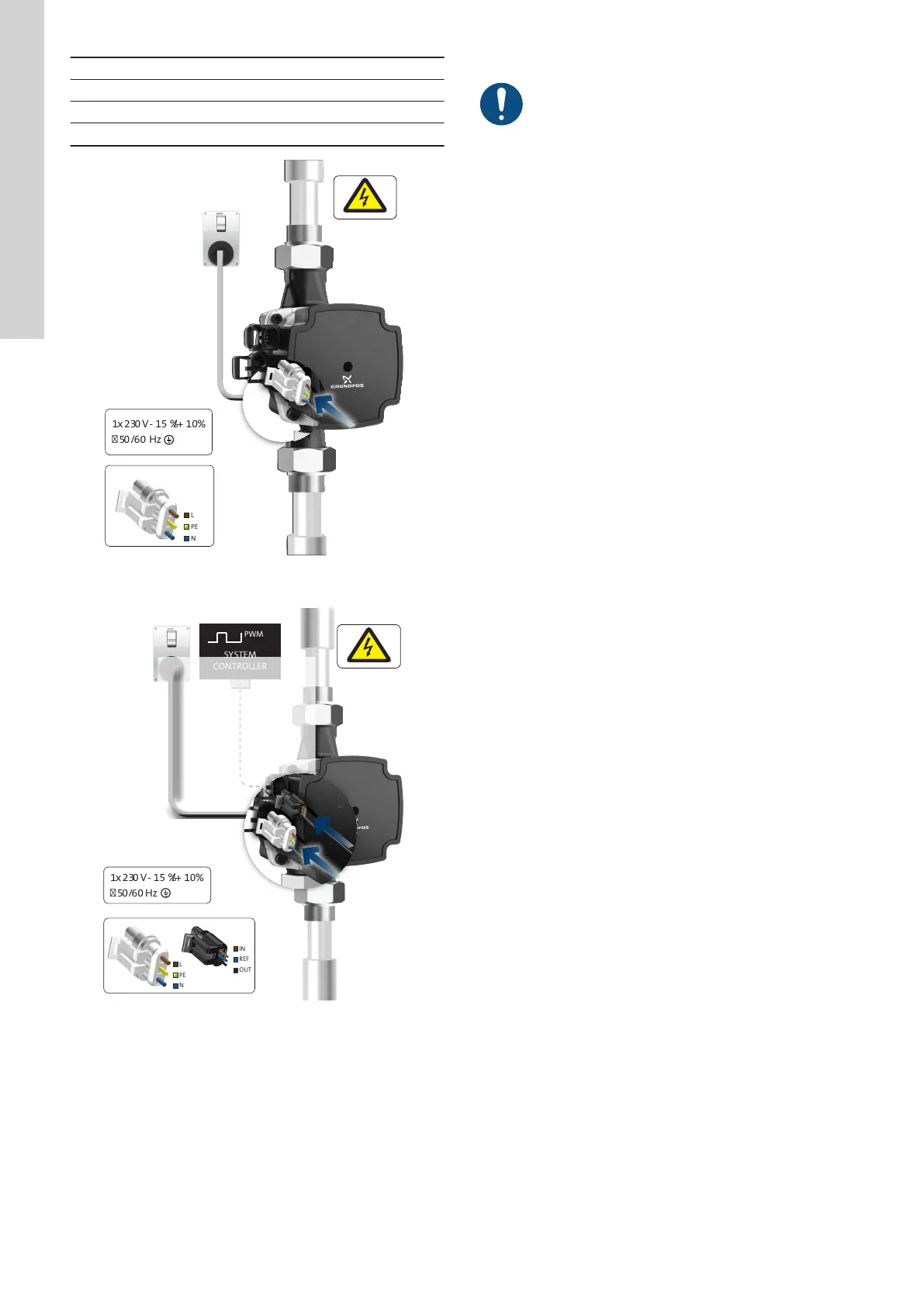
5.4.1 Power supply connection
The pump must be connected to the power supply with the TE
Superseal connector.
Adapters are available for cables with Molex or Volex connectors.
5.4.2
Control signal connection
Connect the signal wires to the correct poles. Otherwise,
the pump may be damaged.
UPM3 pumps are externally speed-controlled. A signal cable is
required to enable the pump control. Otherwise, the pump with
profile A runs continuously at maximum speed, while the pump with
profile C stops.
UPM3 HYBRID pumps are either internally or externally speed-
controlled.
If you set the pump to external control mode (PWM A or C profile)
via the operating panel, you need a signal cable. If you set the
pump to internal control mode, a blind plug can be used to close the
signal connection.
The signal cable connection has three leads: signal input, signal
output and signal reference. The cable must be connected to the
control box by either a FCI or TE Mini Superseal connector.
The cable length can be customised to specific requirements (max.
3 m).
10
English (GB)
 Loading...