5. Electrical connection
All electrical connections must be carried out by a quali-
fied electrician in accordance with local regulations.
The pump is not a safety component and cannot be used
to ensure functional safety in the final appliance.
• The pump requires no external motor protection.
• Check that the supply voltage and frequency correspond to the
values stated on the nameplate.
• The pump must not be used with an external speed control that
varies the supply voltage.
• If an earth leakage circuit breaker is used, check which type it is.
• If an external relay is used, check if it can stand the inrush
current.
5.1 Wiring diagram
TM078819
Example of a mains connected pump with a main switch, backup
fuse, and additional protection.
Pos. no Description
1 Residual Current Device (RCD)
2 Fuse
3 External switch
5.2 Supply voltage
1 x 230 V + 10 %/- 15 %, 50/60 Hz.
The pump is externally controlled via PWM signal or LIN bus signal,
or internally speed-controlled by a frequency converter. The pump
must therefore not be used with an external speed control that
varies the supply voltage, for example phase-cut or pulse-cascade
control.
5.2.1
Reduced supply voltage
Pump operation is ensured above 160 VAC with reduced
performance.
Pumps with PWM and LIN bus control
If the voltage falls below 190 VAC, a low voltage warning is sent via
the PWM or LIN bus signal.
If the voltage falls below 150 VAC, the pump stops and a low
voltage alarm is sent via the PWM or LIN bus signal.
Pumps in internal control mode
If the voltage falls below 150 VAC, the pump stops and gives an
alarm.
Supply
voltage
Pump
performance
Status LED
PWM output
signal
230 VAC Running Green
According to
specification.
<195 VAC Reduced Green Warning
<150 VAC Stopped Red
Alarm
*
*
The pump starts again when the voltage is above 160 VAC and the PWM
output changes to either warning or according to specification depending
on the level.
Related information
11.7 Fault indication on the operating panel
5.3
Earth leakage circuit breaker (ELCB)
5.3.1 Leakage current
The pump mains filter causes a leakage current to earth during
operation.
Leakage current: < 3.5 mA.
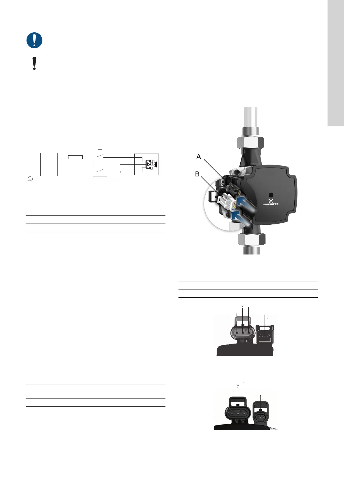
5.4 Control box connections
All control boxes have two electrical connections on one side:
• power supply connection
• signal connection.
If the signal connection is not needed, it can be covered by a blind
plug.
TM079640
Signal connection and power connection
Pos. Description
A Signal connection
B Power connection
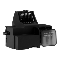
TM068062
Connections FCI
TM064416
Connections Mini SS
9
English (GB)
 Loading...