➔ For 4-20 ma current loop transmitters there are two possibilities:
● USING AN ACTIVE TRANSMITTER WITH ITS OWN INTERNAL DC POWER SOURCE
OR USING A SEPARATE DC POWER SOURCE:
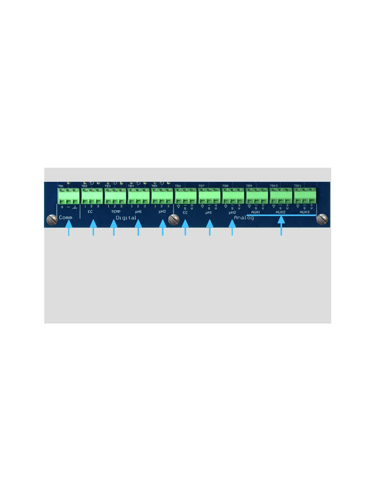
• Connect the – side of the transmitter to terminal 2 of the terminal block.
• Connect the – (ground) side of the transmitter to terminal 1 of the terminal block.
● USING THE MONITOR’S INTERNAL 12 VDC SUPPLY AS THE POWER SOURCE:
• Connect the + side of the transmitter to terminal 3 of the terminal block.
• Connect the – side of the transmitter to terminal 2 of the terminal block.
• The sensor cables may already be connected to the terminal blodks. If they are not or
more sensors are being added, feed the cables through the most convenient strain relief
bushing on the bottom of the box, then connect the wires up to the proper terminal
block. For Anderson digital sensors (1-4), match the ‘1’, ‘2’ and ‘3’ on the sensor cable to
the corresponding numbers on the terminal block.
1 – Signal Ground
2 – Signal Input
3 – +5 VDC supply
Powering Up The Unit
Plug the controller A surge suppressor/uninterrupted power supply should be used to power the controller.
When power is applied to the unit, the display will flash and then show:
Anderson Injectors
Ratio:Guard(tm)
Version Number
Version Date
for a short time as it initializes. It will then display pH, EC, and temperature readings, depending on what
sensors are connected.
5
1. Anderson digital (contacting) EC electrode
2. Anderson digital temperature probe (used for EC temperature correction)
3. pH electrode #1 using Anderson digital signal converter
4. pH electrode #2 using Anderson digital signal converter
5. 4-20 ma analog input for a toroidal EC transmitter
6. 4-20 ma input for analog pH transmitter #1
7. 4-20 ma input for analog pH transmitter #2
8. RS-485 communications connection to J+ Advanced injector controller.
9. The auxiliary inputs AUX1, AUX2, and AUX3 are not currently implemented.
 Loading...