CONSOLE TECHNICAL OVERVIEW
I-3
ENGLISH
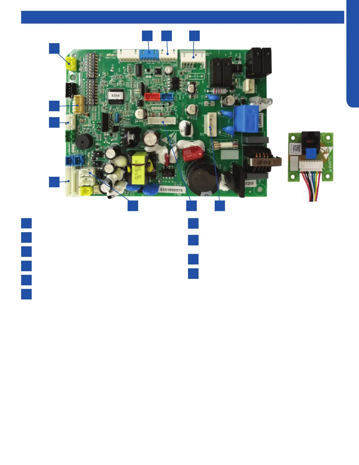
Indoor Circuit Board
Components
1
4
2
5
3
7
10
10
8
6
9
SW2-Damper switch
CN35- Lower damper motor
CN6-DC fan motor
Power supply
CN20-Diagnostic port
CN22- Optional wired controller
6 45
1
7
8
9
5 32
The indoor unit circuit board controls the switching functions of the indoor unit. All control decisions are made by the outdoor
unit ECU. The indoor board has some limited diagnostic capability which will be covered in this manual.
The indoor unit Circuit Board communicates with the outdoor unit ECU via a connection at terminal block screw 3. The data
pulse that sends the communication information can be measured with a voltmeter set to DC voltage range. From the ground
connection at the terminal block to the number 3 screw, voltage should pulse up and down when data is transmitted.
Line voltage to power the indoor unit is made on terminal block connections 1 and 2. Power connects from these terminal
connections to CH-3 and CH-4 on the circuit board. If the board does not respond to command and has no display, check for
line voltage at these connections. When power is present at the indoor board, the Display Power Indicator will be lit. The control
board has a replaceable 3.15A 250V fuse that protects against excessive current. If power is present at the board but the board
does not work, check for continuity through the fuse. Replace if the fuse is open.
The indoor unit sensors are connected at plug CN-13. When testing the calibration of these sensors the wires can be released
from the plug by pressing the tension tab on the side of the plug.
The receiver/display unit, mounted on the front cover of the indoor unit plugs connects to the circuit board at location CN-29.
The blower/fan motor connection is located at plug CN-11.
CN31- Display
CN3-Temperature sensor socket (Tr: ROOM SENSOR,
Tp:PIPE SENSOR)
CN17-WiFi module
RJ45 adapter board
 Loading...