OUTDOOR TECHNICAL OVERVIEW
B-8
ENGLISH
Operations
The outdoor unit is capable of controlling up to 4 individual indoor units. The outdoor unit will vary compressor capacity and
outdoor fan motor speed to match the demand requirement from the indoor units. All capacity and diagnostic decisions are
controlled by the outdoor unit ECU. During any period where the outdoor unit is running, all indoor units must be in the same
mode of operation. If any unit is energized in a mode that opposes the rst indoor unit that was turned on and set to provide
cooling or heating, the opposing unit’s request will be ignored.
Throughout a call for either heating or cooling operation, the temperature sensors in the indoor and outdoor units will provide
critical temperature points to the outdoor unit ECU. If the temperatures being sensed are abnormal or trending to a level that is
potentially going to create overheating of the compressor or freezing of the indoor unit.
The frequency adjustments or system responses to temperature sensors readings are explained in the section Temperature
Sensor Responses.
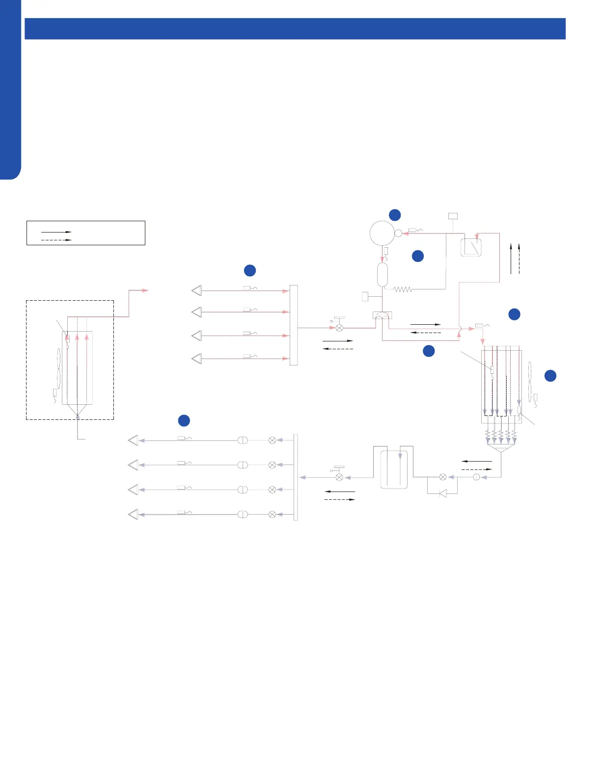
Cooling Mode Sequence of Operation
Comp-
ressor
Discharge temp.
sensor
Oil
separator
Capillary tube
High pressure
switch
4-way valve
Pipe sensor
Toci
Suction temp.
sensor
Low pressure
switch
Accumulator
Gas stop valve
Outdoor
heat
exchanger
temp.
sensor
FAN-OUT
Outdoor
ambient
temp.
sensor
Defrost
sensor
Distributor
Strainer
Check valve
Receiver
Liquid stop vavle
5/8
3/8
Strainer
Unit A liquid pipe temp. sensor
Indoor unit A
Strainer
Unit B liquid pipe temp. sensor
Indoor unit B
Strainer
Unit C liquid pipe temp. sensor
Indoor unit C
Strainer
Unit D liquid pipe temp. sensor
Indoor unit D
Unit A gas pipe temp. sensor
Unit B gas pipe temp. sensor
Unit C gas pipe temp. sensor
Unit D gas pipe temp. sensor
Indoor unit A
Indoor unit B
Indoor unit C
Indoor unit D
4-way valve coil:
OFF
ON
Refrigerant flow in cooling
Refrigerant flow in heating
FAN-IN
Indoor
ambient
temp.
sensor
Indoor
heat
exchanger
temp.
sensor
EEV A
B VEE
EEV C
EEV D
EEV O
φ2.7*φ1.0*55in
1
2
3
4
5
6
7
valve
On a call for cooling, the indoor unit will send the room temperature and set-point requirement to the outdoor unit ECU via the
data signal wire path. The data travels from the indoor unit to the outdoor unit via the wire located on terminal 3. The indoor
unit’s louver will open and the indoor fan motor will start.
The outdoor unit will energize the EEV’s that are controlling refrigerant ow to the calling indoor units. The position of the EEV
valves will be set to a beginning position based upon the outdoor air temperature.
The 4-way valve will be de-energized. After a 3 minute time delay, the outdoor fan motor will be energized. Shortly after the
outdoor fan motor turns on, the compressor will start in low frequency. The operating frequency of the compressor will be
displayed on the Service Monitor Board Display.
The refrigerant in the system will begin to ow. The compressor will discharge hot gas into the oil separator. Oil will be trapped in
the separator and returned to the suction inlet of the compressor via the capillary tube assembly low pressure path.
 Loading...