44
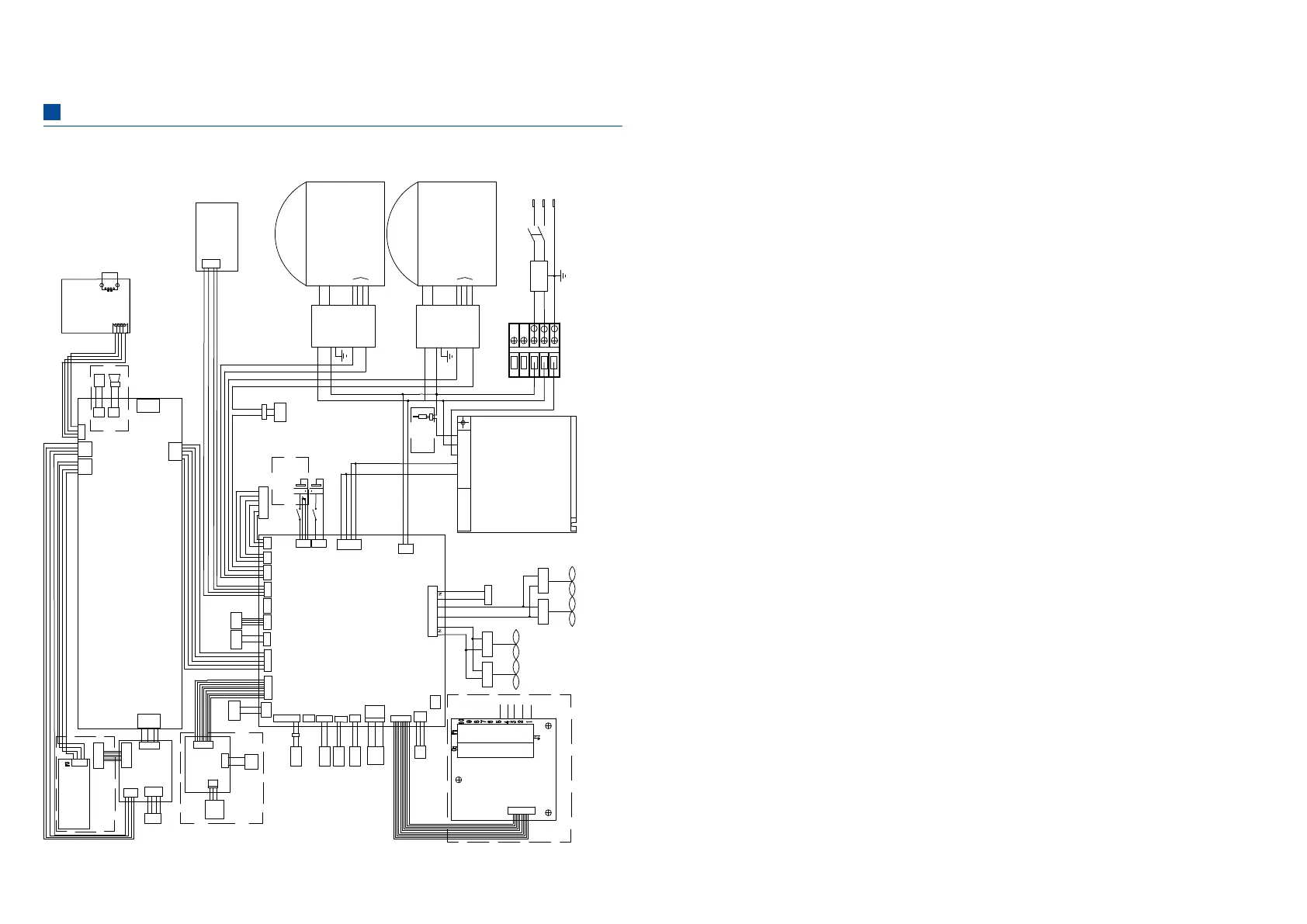
Wiring diagram
•DW-86L579BP/579BPT/729BP/729BPT
Power switch
CN8
Main control board
Variable
frequency
CN6
CN9CN7
CN4
Communication port
for display board
CN10
CN16
CN17
CN20
CN14
CN15
CN13
CN12
CN28
CN25
CN23
CN22
CN27
CN31
CN29
CN2
CN4
WIFI
/GPRS
USB
CN5'
CN1
Display board/touch screen
N
PE
3
2
1
12V
12V
GND
GND
BAT+
NTC+
NTC-
GND
BAT+
NTC+
NTC-
GND
L
N
Compressor for
High temperature stage
5V G B A 12V
GR X TX 5V
5VGTXRX
G'S1 G'S2
L
N
L
N
S1
G
G
S2
L_HTR
L_FAN2
L_FAN1
N
5V G B A1 2V
E
E
DOOR_SW
Electromagnet
lock
Acid-lead
battery
G
12V_BAL
G
12V_RES
G
12V_DOOR
G
S
G
TE1
G
TC
G
TA
G
G
PT100
NC
COM
NO
Outlet for
overload protector
W
V
U
E
W
V
U
E
Input of compressor
motor
W
V
U
E
W
V
U
E
Compressor for
low temperature stage
CN8'
CN5
CN21
USB board
5V
G
TX
RX
CN4
Backup system board
CN11
CN5
P4
CN8
Backup
system
sensor
G
G
PT100
G
+5V
RX
TX
CN3
MIC
SPK
Backup syste m
control board
Optional touch screen
Solenoid
valve
Microphone
Speaker
Optional screen
Communication
from main board
Heater for
pressure
equalization
port
Electromagnet
lock
Door ajar
switch
Magnetic
proximity
door switch
Cold chain
Printer Tricolor light
Battery
Battery
Battery
switch
Battery
switch
Optional
touch screen
Lithium
battery
DC
power
input
Power
Ambient
sensor
Main
sensor
Remote
alarm
contacts
Connector for loads
L
Thermocouple
board
Optional touch screen
Door card
board
Tricolor light
Heat exchanger
temperature
sensor
Condenser
temperature
sensor
Evaporator outlet
Evaporator inlet
Liquid line outlet
for Low te mperature st age
Evaporator inlet
for high tem perature s tage
Evaporator outlet
for high tem perature out let
Pressure con trol
switch for low
temperatu re
switch
Manual reset
pressure switch
for water-cooler models
Terminal conn ectors
Pressure control
switch for low
temperature
switch
Variable
frequency
board
Variable
frequency
board
Inlet for
overload protector
Inlet for
overload protector
Outlet for
overload protector
Input of compressor
motor
Thermocouple
DC current heaters
Power
PE
L
N
-V
+V
Net Net
G
RX
TX
5V
USB-HUB
USB
port
USB
M_UART
M_USB
FINGER
G
+5V
DP-
DP+
CN5
Door card board
Finger print
module
Optional
touch screen
Optional
coldchain
module
condenser
fan 1
condenser
fan 2
condenser
fan 3
condenser
fan 4
F
i
l
t
e
r
5
1.When the unit operates normally, the door frame is slightly warm. The embedded hot gas halo tube
provides free heat to prevent condensation to from on the door frame.
2.Before samples are loaded into a freezer, make sure the unit has reached the set temperature.
Samples should be loaded into the freezer in batches. Each batch should be no more than 1/3 of the
freezer capacity. This process allows the freezer to pulldown the temperature in a reasonable time.
3.The temperature display indicates the temperature where the temperature sensor is mounted
inside the unit chamber, which may vary from the temperature at the center of the freezer, but it will
gradually reach the actual temperature of the freezer over time.
4.Two access ports are available for testing in the back of the freezer. Thermocouple wires can go
through the port holes to reach the interior of the freezer for temperature mapping. The gap of the
holes should be sealed with insulation materials so that the interior temperature is not infl uenced by
the ambient temperature.
5.When cleaning the unit, mild and neutral detergent solution should be used. Never use a hard wire
brush, acid, gasoline, detergent powder, polished powder or hot water for cleaning. These tools and
materials can damage the paint and coating of the unit. Particularly, never use gasoline or a solution
with volatile chemicals to clean plastic or rubber parts.
6.After the freezer runs for some time, a layer of frost usually forms on the interior wall and inner
doors. When the frost gets too thick, the refrigeration eff ect can be impaired. Energy consumption
will increase. If the thickness reaches 5 mm, please use the supplied scrapper to remove the frost.
7.Before removing the frost, temporarily transfer the stored samples to another freezer. This is so that
the temperature does not rise in the unit and damage the samples.
8.Behind the interior walls, there are many refrigeration tubes. Do not use a knife, an ice pick, or a
screwdriver to cut ice and frost. This may damage not only the liner but also the refrigeration tubes.
9.If the freezer is not in use for a long time, please turn off the power and switch off the backup
battery. The power cord should be unplugged.
10.Federal Communications Commission (FCC) Interference Statement
This equipment has been tested and found to comply with the limits for a Class B digital device,
pursuant to Part 15 of the FCC Rules.
These limits are designed to provide reasonable protection against harmful interference in a
residential installation. This equipment generate, uses and can radiate radio frequency energy
and, if not installed and used in accordance with the instructions, may cause harmful interference
to radio communications.
However, there is no guarantee that interference will not occur in a particular installation. If
this equipment does cause harmful interference to radio or television reception, which can be
determined by turning the equipment off and on, the user is encouraged to try to correct the
interference by one of the following measures:
•Reorient or relocate the receiving antenna.
•Increase the separation between the equipment and receiver.
Usage Precautions

 Loading...