OUTDOOR UNIT CONTROLS AND COMPONENTS
PAGE 9
ENGLISH
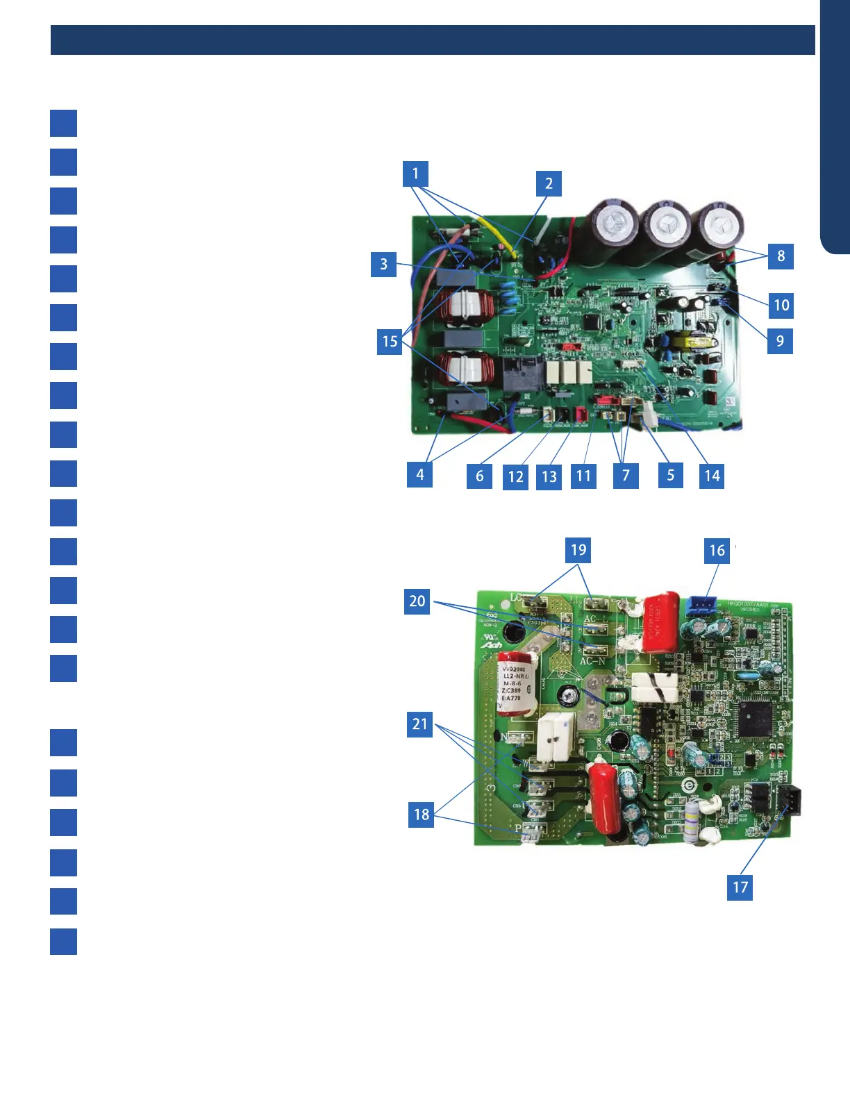
PCB (1) (Outdoor Control PCB)
PCB (2) (Module PCB for 09K )
2
CN3 - Connector for ground
10
CN23 - 5VDC and 15VDC pulsing communication
connection between the PCB and the IPM
6
CN10 - Connector for four way valve coil
4
CNS and CN9 - 230 VAC power to the IPM
connections CN8 (or CN1) and CN9 (or CN2)
12
CN48 - Connector for the base pan heater
8
CN28, CN25 - 310VDC power from the lPM
connections CN1 and CN3
CN1 and CN2 - 230 VAC power from terminal block
connections 1(N) and 2(L), CN6-connector for COM-N
1
CN18, CN20, CN31 - connections for
temperature sensors
7
CN4 -Communication connection between the
indoor board and the outdoor board
3
CN16 - Connector for the electronic
expansion valve
11
CN22 - Connector for DC POWER 15V
and 5V to the IPM
9
CN21- Connector for fan motor
5
CN49 - Connector for COMP heater
13
CN38 - Connector for diagnostic port
14
RV1, RV2, RV3 Varistor
15
CN10 - 5 VDC and 15 VDC power signal from PCB
connection CN22
16
CN11 - Connector for communication between the
control board and the module board
17
CN8, CN9 - 310 VDC single to PCB connections
CN28 and CN25
18
LI (CN3), LO (CN4) - Connector for reactor
19
CN1, CN2 - 230VAC signal from PCB connections CN8
and CN9
CN5, CN6, CN7 - Compressor U, V, and W connections
20
21
PCB
16
●
2
4
5
7
9
15
 Loading...