3
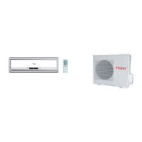
Outdoor unit
Indoor unit
A
B
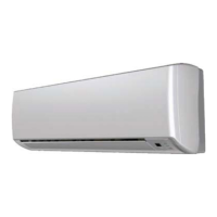
Outdoor unit
Indoor unit
A
B
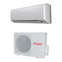
A
B
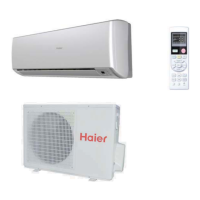
Outdoor unit
Indoor unit
Oil trap
Outdoor unit
Install according to the instructions on the 1st page of this manual
When bending the interconnect tubing, ensure the radius is at least 1 1/4" to 1 3/4",
30mm to 40mm to ensure against crushing the tubing.
ƽ
Connecting the pipe of gas side first makes working easier.
ƽ
Ensure the interconnecting tubing is approved for R410A.ƽ
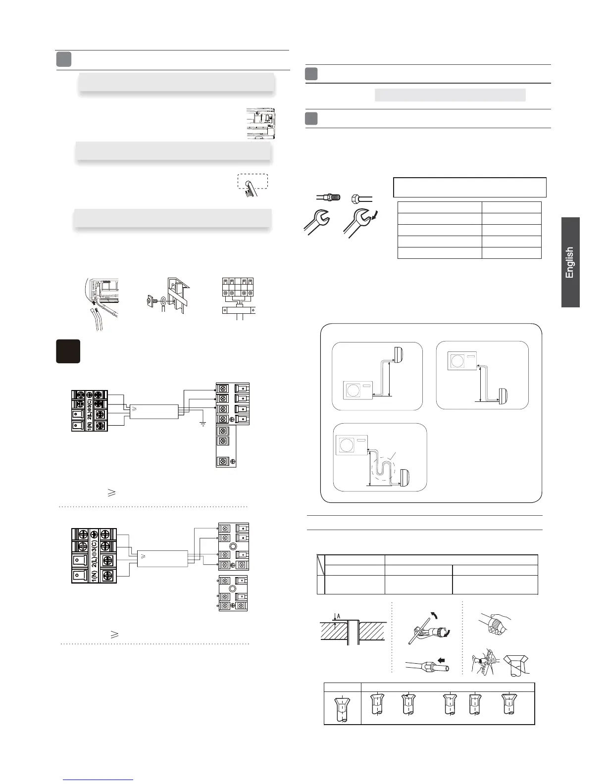
Installation of Outdoor Unit
Half union
Flare nut
Torque wrench
CAUTION
Spanner
Forced fastening without careful centering may
damage the threads and cause a leakage of gas.
Connection of pipes
1.Ifthesupplycordisdamaged,itmustbereplacedbythemanufacturerorits
service agent or a similar qualified person. The type of connecting wire is
H05RN-F
or H07RN-F.
2.IfthefuseonPCboardisbrokenpleasechangeitwiththe
type of
3.Thewiringmethodshouldbeinlinewiththelocalwiringstandard.
4. Use an HVACR circuit breaker or time delay fuse.
T.3.15A/250VAC (Indoor), T.25A/250VAC (Outdoor).
Connecting the indoor/outdoor Electric Cable
Removing the wiring cover
Remove terminal cover at right bottom corner of indoor unit, then take offƽ
wiringcoverbyremovingitsscrews.
1. Insert the cable from the outside into the unit through the same
hole that has the interconnecting tubing.
2.Pulloutthecableonthefrontside,andconnectthecable
making a loop.
Note
When connecting the cable, confirm the terminal number of indoor and
outdoor units carefully. If wiring is not correct, the unit will not operate
When connecting the cable after installing the indoor unit
When connecting the cable before installing the indoor unit
Indoor unit
)C
(3
)
N
(1
)L(
2
)
C
(3
)
N
(
1)L(2
^
Outdoor unit
{
Indoor unit
Outdoor unit
1
2
N
2
)
(
3
(C)
L
1
)
(
•
Max.Elevation: Amax
= 32ft / 10m (09k / 12k)
= 50ft / 15m (18k / 24k)
•
In case the elevation A is more
than 15ft / 5m, oil trap shoud be
installed every 5~7m
•
Max. Length: Bmax
= 50ft / 15m (09k / 12k)
= 80ft / 25m (18k / 24k)
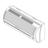
HSU09VHG(DB)-W
HSU12VHG(DB)-W
HSU18VHG(DB)-W
HSU24VHG(DB)-W
ƽ
ƽ
ƽ
Insert the cord from the back side of the unit, then pull it out on the front side.
Fasten the unit wire harness to the conduit holder using the lock nut.
Position the conduit holder to its original state using screw.
Power
Wiring
4wire 18AWG
Control Wiring
Power cable:
2wire with ground 16AWG
Power cable:
2wire with ground 12AWG (4G0.75 mm )
Power
Wiring
4wire 18AWG
Control Wiring
Pipe Diameter(ǿ) Fastening torque
Liquid side6.35mm(1/4") 18N.m/13.3Ft.lbs
Liquid/Gas side9.52mm(3/8") 42 N.m/30.1Ft.lbs
Gas side 12.7mm(1/2") 55N.m/40.6Ft.lbs
Gas side 15.88mm(5/8") 60 N.m/44.3Ft.lbs
properly and could cause a defect.
(4G0.75mm )
2
(4G0.75 mm )
2
(4G0.75mm )
2
2
Ensure that no dirt or debris enters the tubing. The standard tubing length is 15 ft., 5M.
If a different length is required, adjust the refrigerant amount by 1/4 oz/ft, 20 g/M for the
9k, 12k and 18k models. For the 24k model, adjust by 1/2 oz/ft, 40 g/M.Before opening
the service valves, evacuate the interconnecting tubing and indoor unit. Follow the
instruction in section 5 on page 4.
Pipe cutting is carried out with a pipe cutter and burs must
ƽ
be removed.
After inserting the flare nut, flaring work is carried out.
ƽ
CuttingandFlaringWorkofPiping
FlaretoolforR410A Conventionalflaretool
Clutch-type clutch-type(Rigid-type) Wing-nut type (Imperial-type)
A
0~0.5mm
1.0~1.5mm
1.5~2.0mm
0~1/51 inch
3/76 ~1/17 inch
1/17 ~1/8 inch
Flare tooling die
1.Cut pipe
2.Remove burs
3.Inserttheflarenut
4.Flare pipe
Lean
Damage of flare Partial Too outside
Correct Incorrect
Crack
 Loading...