127
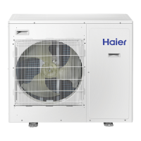
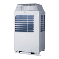
Outdoor Unit
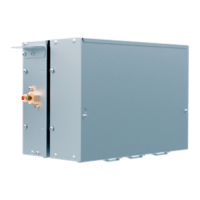
Electric Control
2) Valve box parameters observation
The parameters of indoor unit address 1-64 can be observed: SW9 and SW10 are valve box numbers; the range of
SW11 is 3-14, regarding observed valve box parameters.
SW9 SW10 System address
7
0-15
Unit 1-16
(
valve box PCB address dial-up 0#-15#
)
8 Unit 17-32
(
valve box PCB address dial-up 16#-31#
)
9 Unit 33-48
(
valve box PCB address dial-up 32#-47#
)
10 Unit 49-64
(
valve box PCB address dial-up 48#-63#
)
SW11 Function Display with digital tube LED1~4
3 Valve box program version
If communication is normal, show the indoor unit program version
(one decimal). If communication stops, normally show "0000" (failing
communication for 5 consecutive rounds). If communication has been
abnormal, show "----".
For example,"F0.1" means valve box version is V0.1
4 Valve box mode and failure
LED1: show valve box mode O: Stop C: Cooling H: Heating
LED2: show"-"
LED3-4: show valve box failure code, if there is no fault, show 0.
For example,"H-01", means the valve box current mode is heating; if
there is failure, show code "01".
5
Solenoid valve status of valve
box
LED1: BS4WV: 1 ON 0 OFF--Far left
LED2: BSSV1: 1 ON 0 OFF
LED3: BSSV2: 1 ON 0 OFF
LED4: BSSV3: 1 ON 0 OFF
6
Total indoor units connected to
the valve box
Note: 8 units as maximum
7
Address of 1st indoor unit
connected to valve box
"----"means be connected failed.
8
Address of 2nd indoor unit
connected to valve box
"----"means be connected failed.
9
Address of 3rd indoor unit
connected to valve box
"----"means be connected failed.
10
Address of 4th indoor unit
connected to valve box
"----"means be connected failed.
11
Address of 5th indoor unit
connected to valve box
"----"means be connected failed.
12
Address of 6th indoor unit
connected to valve box
"----"means be connected failed.
13
Address of 7th indoor unit
connected to valve box
"----"means be connected failed.
14
Address of 8th indoor unit
connected to valve box
"----"means be connected failed.
 Loading...