20 HARDI
®
N-SERIES 3-PT SPRAYER DIAPHRAGM OPERATOR'S MANUAL
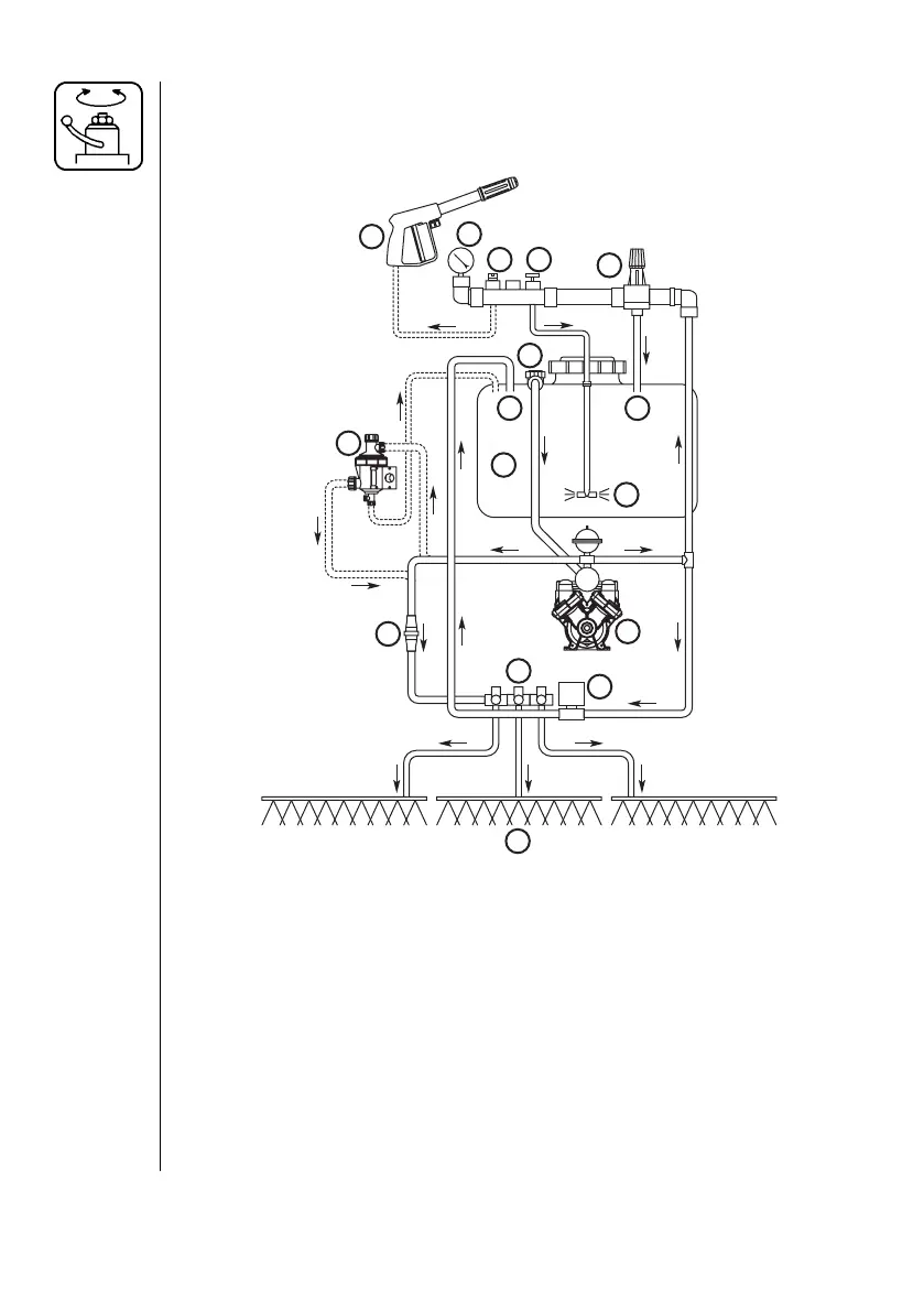
4.4 EC-3 Plumbing Diagram w/optional Rate Controller
Review and study the following diagram. By following the fl ow through
the diagram, you will better understand the various functions of your
sprayer system.
1. Top Suction 9. Tank
2. Diaphragm Pump 10. Bypass Returns
3. Pressure Relief Valve* 11. Self-Cleaning Filter (optional)
4. Agitation Valve 12. Boom Distribution Valves
5. Spraygun Valve (optional) 13. Boom
6. System Pressure Gauge 14. Flowmeter
7. Spraygun (optional) 15. Pressure Regulator
8. Agitation
*Turn Pressure Relief Valve clockwise all the way in when used with
the optional Rate Controller. Refer to Maverick Operator's manual for
adjustment of the controls.
1
3
8
9
7
12
13
2
4
5
6
10
11
14
15
10
Fig. 11