11
www.hardlifeutility.c om
Figure 8 (C2640)
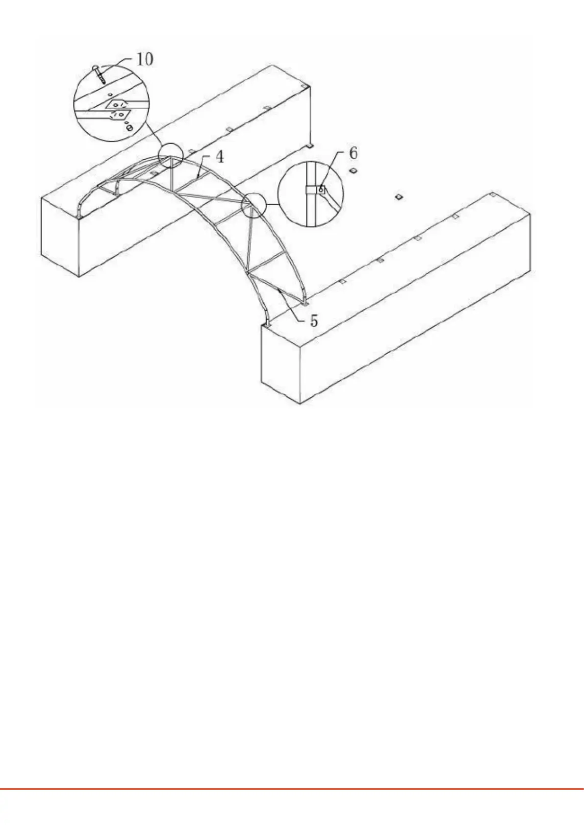
FRAME INSTALLATION
1. Erect the assembled rst arch to the standing position. Insert one end of the assembled arch into one base
plate and force the other end of the arch into the opposite base plate, as shown in Figures 5, 6, 7, and 8.
2. Install the second arch in the same manner immediately aer installing the rst arch, and connect the
two arches using connection purlins (component code 4). Secure the purlins using M10 X 80 mm bolts
(component code 10), as shown in Figures 7, 8, 9, and 10. ere are ve pieces of connection purlins be-
tween two group arches.
3. Install the third arch and connect the connection purlins. Install all the other arches in the same manner
and connect the purlins, as shown in Figures 9 and 10.
4. Finally, install the supporting tubes (component code 5) between the rst and last group of arches and
connect using M8 x 70 mm bolts (component code 9) and clips (component code 6), as shown in Figures
7, 8, 9, and 10.
5. Tighten all the frame bolts, connection purlins, and supporting tubes adequately before installing the roof
cover.
 Loading...