9
3-90-08101R23_06/13
Venting
Design
Therstthingneededisdecidingwhereandhowthefurnace
willbeinstalled.
ThingsthatneedtobetakenintoconsiderationareVenting,
Supply and Return Ducting, Electrical, and Condensation
Drainage (ifA/C is installed). Don’t forget access to the
furnaceforservice.
Whenthereturnairinletpositionisknown,thelterboxand
distributionblowercanbeinstalled.Afterthefurnaceisset
intoplace,theventingcanbecompleted.
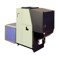
Venting
Use 4” pellet vent pipe only.
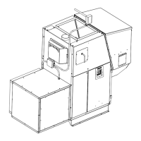
A combustion blower is used to extract the combustion
gasesfromtherebox.Thiscreatesanegativepressurein
thereboxandapositivepressureintheventingsystemas
showning.2.Thelongertheventpipeandmoreelbows
usedinthesystem,thegreatertheowresistance.Because
of these facts, we recommend using as few elbows as
possible and 30 feet or less of vent pipe. The maximum
horizontalrun should not exceed 18 feet. Remember, the
horizontal pipe sections will accumulate with y-ash rst.
Keepthisareaclean.
Be sure to use wall and ceiling pass through ttings
which are approved for pellet vent pipe when going
through combustible materials. Besuretouseastarting
collar to attach the venting system to the furnace. The
starting collar must be sealed to the furnace ue collar
with high temp silicone caulking or aluminum tape, and
screwed into the ue collar at least three (3) places.
Vent Pipe
4”pelletventpipe(knownasPLvent)isconstructedoftwo
layerswithairspacebetweenthelayers.Thisairspaceacts
asaninsulatorandreducestheoutsidesurfacetemperature
toallowaclearancetocombustiblesaslowas2inches.This
clearanceistestedandlistedbythepipemanufacturers.
Thesectionsofpipelocktogethertoformanairtightseal
in most cases; however, in some cases a perfect seal is
notachieved.Forthisreasonandthefactthatthefurnace
operateswithapositiveventpressure,we specify that all
joints within the structure should also be sealed with
high-temp silicone.
Fig. 1
NOTE: Read and follow all of the vent pipe
manufacturers’ instructions on the proper installation
and support of the vent pipe. Adhere to all clearances.
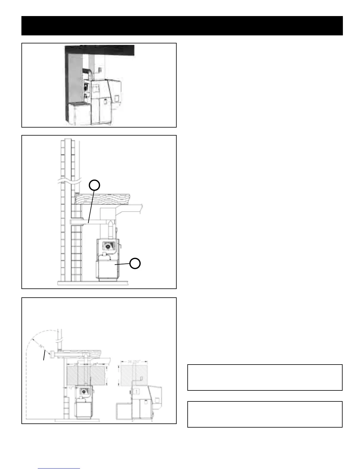
Clearances and Venting
Theshadedareasarewheretheclearances
forthePLventpipemustbemaintained
at3”.Aftertheventingleavestheshaded
area it may be installed as per the vent
manuafacturerinstructions.(Onlylistedwall
pass-throughsandrestopsmaybeused.)
See NOTES:
on page 12
16”
16”
NOTE: Use only 4” diameter “PL” venting system.
Be sure to inspect and clean exhaust venting system
frequently.
Fig. 2
+
-
 Loading...